Over the holiday I have taken off on another tangent instead of building an amp.
I was trying to get better measurements of tube distortion so I can sort the used tubes I have on hand. I'm focusing on triode strapped pentodes including 6CB6, 6EJ7, 6J51P, 6JC6 and 6J9P.
I built a test box with :
(1) FET with Zener regulator to help filter the B+ comming in
(2) Switch Selectable tube anode loads of FET/Bipolar current source, Cascode DN2540 current source, and Gyrator.
(3) Fully bypassed adjustable cathode resistor.
(4) A Current Source Loaded FET Source Follower to buffer the output signal.
(5) DC input for cathode heater supply
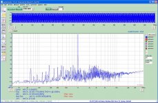
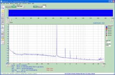
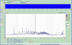
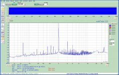
This combination allows me to get measurements that seem to be 20dB better than I had previously made. The two screen shots show examples of previous and current measurements.
Is the data presented in the second FFT realistic for such measurements?
Is the distortion level in line with what should be expected for a current source loaded triode strapped pentode with fully bypassed cathode resistor?
Is the background noise level what should be expected?
In other words am I getting true representative data or do I still have a way to go to be able to accurately measure tube distortion and S/N ratio?
I was trying to get better measurements of tube distortion so I can sort the used tubes I have on hand. I'm focusing on triode strapped pentodes including 6CB6, 6EJ7, 6J51P, 6JC6 and 6J9P.
I built a test box with :
(1) FET with Zener regulator to help filter the B+ comming in
(2) Switch Selectable tube anode loads of FET/Bipolar current source, Cascode DN2540 current source, and Gyrator.
(3) Fully bypassed adjustable cathode resistor.
(4) A Current Source Loaded FET Source Follower to buffer the output signal.
(5) DC input for cathode heater supply
This combination allows me to get measurements that seem to be 20dB better than I had previously made. The two screen shots show examples of previous and current measurements.
Is the data presented in the second FFT realistic for such measurements?
Is the distortion level in line with what should be expected for a current source loaded triode strapped pentode with fully bypassed cathode resistor?
Is the background noise level what should be expected?
In other words am I getting true representative data or do I still have a way to go to be able to accurately measure tube distortion and S/N ratio?
Attachments
Hi Steven,
I've been using a similar test circuit based on DN2540 cascoded CCS and fixed bias. I had some ground loops issues which blew some of the interface ICs from the pete millett's interface and still got some 100Hz level a bit higher in my perspective. Otherwise the noise floor is below 90dB and generally get 80-90dB SNR. Either way, it's very useful to identify misaligned electrodes in DHTs and refine operating points....
Happy New Year!
Cheers,
Ale
The title to this thread is because I found that for every current source I tried, and for every FET I tried, Source Follower induced distortion was inversely related to current.
At 3 mA and below, current source induced FET distortion dominated tube distortion!
At 2mA second harmonic is at about -74dB wrt 2.82Vrms 0dB ref.
At 20mA second harmonic is down below -100dB, a difference of over 25dB!
At 3 mA and below, current source induced FET distortion dominated tube distortion!
At 2mA second harmonic is at about -74dB wrt 2.82Vrms 0dB ref.
At 20mA second harmonic is down below -100dB, a difference of over 25dB!
Attachments


I tried a ZVN0545 and got the same results at 3mA.
I tried pairing it with a LND150 current source at 1.1mA(max I could get) and got high distortion as well.
I tried pairing it with a LND150 current source at 1.1mA(max I could get) and got high distortion as well.
All are mosfets. I was suggesting a jfet of low current, I recently tested a 2sk170 gyrator on a cx301a running at 3ma with superb results...
Have a great new year!!
Ale
Have a great new year!!
Ale
Because we use Source Followers made of MosFets with current sources as the driver stage of tubes.
I believe they may be a significant a source of distortion.
I believe they may be a significant a source of distortion.
Steven,
I'm working on my driver for the 4-65a SE amplifier. It's a 46 (triode-strapped) in filament bias loaded with a single IXYS MOSFET. It should get the best out of the 46. The spice simulation gets 0.15% at 200Vpp. Currently I tested it on the bench with limited tester signal which gives 0.04% at 10Vrms.
Gyrators in mu-follower are fantastic as drivers specially in class A2. Will give the flatest load line, minimum distortion and lowest output impedance...which is a plus for an A2 driver. In this case, the FET distortion is minimum given the circuit used....
Cheers,
Ale
All of my tests are at 2.8Vrms (8.24Vp-p actually) as that is the largest signal I can feed into my sound card without clipping. I try to keep the test signal between -.25dB and -.5dB if possible.
I've seen several tubes with 0.025% thd under these conditions.
I plan on reconfiguring the socket and testing some EF86s as well to see how they compare.
I've seen several tubes with 0.025% thd under these conditions.
I plan on reconfiguring the socket and testing some EF86s as well to see how they compare.
Happy New Year folks!
My amp: D3a, green LED bias, 10mA cascode CCS as anode load, capacitor coupling to FET source follower (5mA), direct coupling to 300B, 5K:8 OPT.
At A2 mode 8W output (A1 limit about 6W power) CCS out is 95V RMS, 0.2443% THD, source follower output (300B grid) also 95V, 0.2430% THD.
My amp: D3a, green LED bias, 10mA cascode CCS as anode load, capacitor coupling to FET source follower (5mA), direct coupling to 300B, 5K:8 OPT.
At A2 mode 8W output (A1 limit about 6W power) CCS out is 95V RMS, 0.2443% THD, source follower output (300B grid) also 95V, 0.2430% THD.
The title to this thread is because I found that for every current source I tried, and for every FET I tried, Source Follower induced distortion was inversely related to current.
Hey,
One important parameter is missing: Load of the SF! It would be natural that distortion lessens with more current if load is lowZ. Have you calculated needed drive current??
The load is an M-Audio 192 sound card, with a specified input impedance of 10K.
4V peak into 10K is 0.4mA peak. Rule of five says over 2mA should be good. Maybe just not good enough?
4V peak into 10K is 0.4mA peak. Rule of five says over 2mA should be good. Maybe just not good enough?
Last edited:
The rule of 5 was probably written when -30 db was considered good. -70 couldn't be measured then. A follower can source more current than it can sink, and the sink current is controlled by the source resistance. The lower the resistance, the lower the asymmetry. This is why the second harmonic is affected most by current. Yes, the load impedance and capacitance matters because of the asymmetric output impedance of the follower.
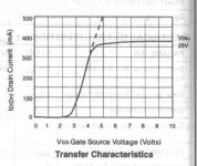
With MOS devices, the "Threshold Region" of low drain current is the worst-performing region.
Diodes (the new Zetex owner) don't publish the curves any more, so here is a grab from the old data book, illustrating the threshold region of the ZVN0545.
At low current the Id vs Vgs characteristic is highly curved, compared to higher-currents.
In effect, for a source-follower, this means that the gm is changing as the load current increases (eg due to capacitance charging).
The output drive impedance for the FET is 1/gm, so the distortion arising from the load is also changing as the current increases.
For a follower, the small-signal output voltage is related to gm and the load RL by:
Vout/Vin = RL/(RL + (1/gm))
so the nonlinear component of gm is sure to cause distortion.
gm for the ZVN0545A is about 100ms at 100mA - and a great deal lower at 3mA.
The bipolar transistor performs much better at low current, but the base current brings problems of its own.
.
Attachments
What will be the best setup to test Pentode distortion? Clearly the approach with a CCS used in a triode is not practical as the gain of the stage will be too high and difficult to measure in practice. Options would be a resistor load but probably better a choke or gyrator?
How have you done this before?
Thanks
Ale
How have you done this before?
Thanks
Ale
I plan on using a gyrator as the anode load when I test in pentode mode. I already have one built in to the test-set.
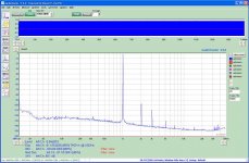
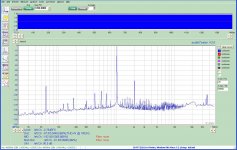
I built a buffer using a LF353. FFT 1 is the low distortion oscillator throught the buffer. FFT 2 is with the SF but no buffer, and FFT 3 is with the SF and buffer.
The buffer has reduced the 3rd and 4th harmonics, but second is worse.
I tried two different current sources and a gyrator and the results are the same.
I have also tried different tubes and get the same results.
I've tried the tube driving the buffer without the SF and the results are the same.
I'm at a loss for the high second order harmonic with the SF and buffer.
Out of curiosity, I tried a resistor which resulted in the same operating point and it looked really bad compared to the CS and Gyrator!
Attachments
Steven,
Are these triode tests? What is the output level? 10Vrms?
Regarding the buffer, I think I read somewhere that the op amp could be forced in class A by adding a couple of CCSs and improve the distortion. Not an expert in op amps, so probably someone can shed some light.
The RL (or RA) will impact the distortion. If you are loading the valve with a CCS or Gyrator, then the input impedance of your soundcard/test box is the one driving distortion up. If using a resistor load, then this resistor is in parallel with the soundcard input impedance (as in case of CCS/gyrator) but given that the value is typically below 100k this is what drives distortion even higher.
Coming back to pentode test setup, the gain of the pentode is typically gm*Ra. If we use a gyrator then the impedance at the testing frequency (e.g. 1kHz) has to be not that high (e.g. 20k for a gm of 5mA/v ) otherwise the gain will be too high and clip easily?
Ale
- Status
- Not open for further replies.
- Home
- Amplifiers
- Tubes / Valves
- FET Source Follower Distortion