Hi all!
Seeking help from this transformer ATX power supply?!
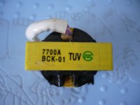
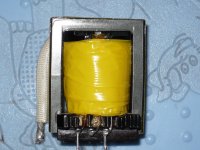
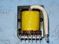
Here are some pictures of the ferrite Trafo (Figure 1-mark, Figure 2 - primary; Figure 3 - secondary; Figure 4 - PCB-back).
In one picture was given to his label, and the other two carried out the primary and secondary. A picture on the back of a picture of the PCB on the back side of the transformer was taken out then.
Question: Who performs the secondary transformer for 12V and for 5V that?
And where is possible to find data for this transformer this mark on the Internet?
I expect a quicker response, of course, if possible!
A big thank you in advance for your help!
Seeking help from this transformer ATX power supply?!
Here are some pictures of the ferrite Trafo (Figure 1-mark, Figure 2 - primary; Figure 3 - secondary; Figure 4 - PCB-back).
In one picture was given to his label, and the other two carried out the primary and secondary. A picture on the back of a picture of the PCB on the back side of the transformer was taken out then.
Question: Who performs the secondary transformer for 12V and for 5V that?
And where is possible to find data for this transformer this mark on the Internet?
I expect a quicker response, of course, if possible!
A big thank you in advance for your help!
Attachments
Last edited:
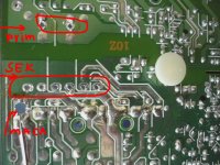
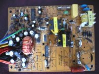
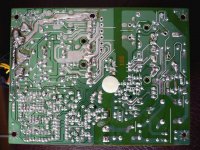
Show us a good picture of the back and front of the entire PCB without the red markings, but mark on the where the 5V and 12V output pins or wiring harness is. From that (if the pictures are good enough) we should be able to trace the circuit and identify 5V and 12V transformer leads.
Show us a good picture of the back and front of the entire PCB without the red markings, but mark on the where the 5V and 12V output pins or wiring harness is. From that (if the pictures are good enough) we should be able to trace the circuit and identify 5V and 12V transformer leads.
Here are images of the front and back of the PCB ATX-power supply, where the transformer was taken out!
I think these pictures are marketed!
Regards
Attachments
See attachment. I do not know the manufacturer identity or specifications of the transformer.
Uploaded with ImageShack.us
An externally hosted image should be here but it was not working when we last tested it.
Uploaded with ImageShack.us
An externally hosted image should be here but it was not working when we last tested it.
See attachment. I do not know the manufacturer identity or specifications of the transformer.
An externally hosted image should be here but it was not working when we last tested it.
Uploaded with ImageShack.us
An externally hosted image should be here but it was not working when we last tested it.
http://imageshack.us/photo/my-images/641/pcbatxtop.jpg/
Thanks for your help and Cheers!
Last edited:
I saw on another forum you wrote:
http://www.diysmps.com/forums/showthread.php?198-To-rewind-the-ATX-power-supply...]
I doubt you can do this. 2 x 32VAC @ 6A is 384VA, the transformer is not capable of that, this power supply has a fake (fraudulent) 500W rating, it is really closer to a 200W PSU. Notice that even the bridge rectifier before the large capacitors you removed (4 diodes), handling AC line voltage seem to only be 2A rated (maybe 3A rated, it is hard to tell their exact size from the picture). Everywhere this PSU is built for less than half the rated wattage and the generic capacitors will probably fail - it just isn't a good candidate/host for spending a lot of time building a new SMPS.
The size transformer you'll probably need is too big to fit in the available space on the PCB. I also wonder if the switching transistors would fry at this load, but maybe not as using it for audio means a lower average current than 6A on the secondary.
Also you would probably need to remove and replace the other components on the PCB after the transformer, use a different controller or alter the feedback loop. While these things "might" be possible, I am wondering how you plan to do this since you hadn't yet been able to identify the 5V and 12V circuits as a preliminary step.
http://www.diysmps.com/forums/showthread.php?198-To-rewind-the-ATX-power-supply...]
radio said:"Hi all!!
It has a transformer with the sign TUV BCK-01 (ATX-power supply Deluxe PA-500W).
Question: How do i rewind this transformer: Primar as winding wire lacquered with which section? trespass on the secondary i want to get around and about 2x32Vac and currents up to 6A. Which section of wire that applied polish motam secondary?"
I doubt you can do this. 2 x 32VAC @ 6A is 384VA, the transformer is not capable of that, this power supply has a fake (fraudulent) 500W rating, it is really closer to a 200W PSU. Notice that even the bridge rectifier before the large capacitors you removed (4 diodes), handling AC line voltage seem to only be 2A rated (maybe 3A rated, it is hard to tell their exact size from the picture). Everywhere this PSU is built for less than half the rated wattage and the generic capacitors will probably fail - it just isn't a good candidate/host for spending a lot of time building a new SMPS.
The size transformer you'll probably need is too big to fit in the available space on the PCB. I also wonder if the switching transistors would fry at this load, but maybe not as using it for audio means a lower average current than 6A on the secondary.
Also you would probably need to remove and replace the other components on the PCB after the transformer, use a different controller or alter the feedback loop. While these things "might" be possible, I am wondering how you plan to do this since you hadn't yet been able to identify the 5V and 12V circuits as a preliminary step.
Last edited:
Hi Sirs
I see that you understand the SMPS!
I want to create an SMPS for the subwoofer in the car under this schematic (see schematic).
So please do help because I have a problem with ferrite transformer how to create one. At the intersection of town core (transformer type), how many coils should have the primary section to which and how many turns of wire with which the secondary wire gauge (2x35V/2x4A)?
Thanks and Cheers !
Attachments
Last edited:
I would rather use peak current mode control for this low voltage push-pull just to be sure that transformer saturation is avoided.
Usually, ring cores (toroids) are the best choice for this car amplifiers...
The size of magnetic core is directly related to the amount of energy you want to transfer, switching frequency and converter topology.
For calculating the amount of turns, just use Faraday's law.
Usually, ring cores (toroids) are the best choice for this car amplifiers...
The size of magnetic core is directly related to the amount of energy you want to transfer, switching frequency and converter topology.
For calculating the amount of turns, just use Faraday's law.
I would rather use peak current mode control for this low voltage push-pull just to be sure that transformer saturation is avoided.
Usually, ring cores (toroids) are the best choice for this car amplifiers...
The size of magnetic core is directly related to the amount of energy you want to transfer, switching frequency and converter topology.
For calculating the amount of turns, just use Faraday
Please if you are able to give more detailed instructions about making this ferrite trafo for this SMPS?I would rather use peak current mode control for this low voltage push-pull just to be sure that transformer saturation is avoided.
Usually, ring cores (toroids) are the best choice for this car amplifiers...
The size of magnetic core is directly related to the amount of energy you want to transfer, switching frequency and converter topology.
For calculating the amount of turns, just use Faraday's law.
thanks and cheers !

Your schematic is far from being complete. You have many things to think of before starting transformer design.
Just imagine what will happen if you make a short circuit on the output...
 . An overcurrent/short-circuit protection is a must!
As pwm controller you can use UCC38083.
Just imagine what will happen if you make a short circuit on the output...
. An overcurrent/short-circuit protection is a must!As pwm controller you can use UCC38083.
Hi mflorin!Your schematic is far from being complete. You have many things to think of before starting transformer design.
Just imagine what will happen if you make a short circuit on the output...
As pwm controller you can use UCC38083.
Mr give help about SMPS for the subwoofer amplifier with TDA7294?
Tell SMPS project or design!??
thanks and cheers !!
Why don't you try TOP249YN which has many features and protection including PF correction easy to build too, and cheaper in price also.
- Status
- Not open for further replies.
- Home
- Amplifiers
- Power Supplies
- Ferrite transformer SMPS-help!