Hi everyone,
This amp came to me after crapping out and vising a few other techs...shady back-story of the amp being purchased second hand with only 2 power tubes installed, and it has never worked with all 4 tubes. I can feed a signal into the amp and measure the output at the "preamp out" as well as the input of the driver tube.
Schematic here
Here are some findings:
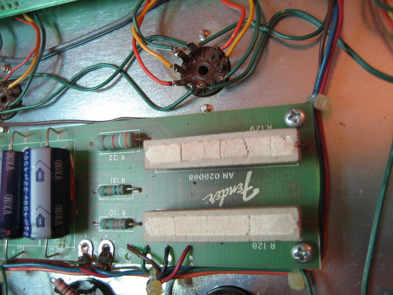
R302/R303 (?) burned out and were previously replaced

R128/R129 look terribly heat damaged but still hold their values.
The output tubes and driver tube test OK. The 6L6 plates are about 480v and are all pulling 20mA cathode current a piece. The choke has a resistance of 150ohms but also measures a moving resistance to ground - the DVM starts at 20meg and works its way down to 450K slowly, with one leg of the choke removed. The OT Primary measures 76ohm from end to end, 37/39ohm from each end to CT. The OT Secondaries are as follows:
WH-OR (balanced out) 0.5ohm
GN/YL - BK (gnd) 0.4ohm
GN/YL - GN 0.2ohm
GN/YL - YL 0.7ohm.
In addition, I found the feedback line between GN/YL and the driver tube was severed. Also the NC ground shunt on the speaker output was bent so that there was never a ground connection if no speaker was connected.
I don't usually take on these modern Fenders, I find their circuits to be a bit messy. Any ideas about what to start testing? Could the OT be shot?
Thanks
adam
This amp came to me after crapping out and vising a few other techs...shady back-story of the amp being purchased second hand with only 2 power tubes installed, and it has never worked with all 4 tubes. I can feed a signal into the amp and measure the output at the "preamp out" as well as the input of the driver tube.
Schematic here
Here are some findings:
R302/R303 (?) burned out and were previously replaced
R128/R129 look terribly heat damaged but still hold their values.
The output tubes and driver tube test OK. The 6L6 plates are about 480v and are all pulling 20mA cathode current a piece. The choke has a resistance of 150ohms but also measures a moving resistance to ground - the DVM starts at 20meg and works its way down to 450K slowly, with one leg of the choke removed. The OT Primary measures 76ohm from end to end, 37/39ohm from each end to CT. The OT Secondaries are as follows:
WH-OR (balanced out) 0.5ohm
GN/YL - BK (gnd) 0.4ohm
GN/YL - GN 0.2ohm
GN/YL - YL 0.7ohm.
In addition, I found the feedback line between GN/YL and the driver tube was severed. Also the NC ground shunt on the speaker output was bent so that there was never a ground connection if no speaker was connected.
I don't usually take on these modern Fenders, I find their circuits to be a bit messy. Any ideas about what to start testing? Could the OT be shot?
Thanks
adam
AMps are amps, circuits are circuits. This amp works the same way they did 30 years before it. It might have MORE circuitry, but tubes are tubes. Only part of this amp that is cosmic is the footswitch comparator.
Power supply burnup? Your R302, R303 are 47 ohm, not 470, and are classic Fender heater hum balance pseudo center tap. Only reason for them to burn up is something using them as a path to ground, almost always a shorted power tube. Short high voltage to heater, and they burn up. ANother way they burn up is when someone snaps the center alignment post off a power tube, then sticks it in the socket anyway. 7 chances out of 8 will be wrong. And if you think of the heater inside the tube as a wire, then pin 2 is shorted to pin 7 of the tube. If you stick that in a socket facing another direction, I leave it to you to determine what shorts to what. Hint: off by one pin and 2-7 becomes 3-8, and so on.
The two large 10 watt resistors are probably OK. They are 10 watt because they do get hot. They form a brute force voltage divider on the B+.
Look on your schematic for those sets of resistors.
Circuit boards are insulators, unless they are burnt. ANY part that turns to charcoal is now carbonized and so conductive. Maybe you are OK at 6v under those 47 ohm resistors, but really, all that charred material ought to be scraped away.
testing the choke with a meter won't probably work well. You can check for a hard short to frame, but will never detect shorted turns. And you need to disconnect both ends of it to do anything else. Any readings you take with an end connected still will be trying to charge up caps in the circuit with your meter, hence the shifting reading. It's probably fine anyway.
So the preamp works. Great. You have all the voltages at the power tubes? APparently, if they bias up. You have checked for any signs of burnt around all four tube sockets? I hope so.
Worry about the NFB and output jack later.
SO the power amp fires up, the power tubes bias up, and you have no output. Power up and inject a signal at the grid of each power tube. I just use a wire. Leave the black probe of your meter unconnected and sit it somewhere secure. Now probe with the red probe at each power tube grid - pin 5. Do you get any noise out the speaker with each touch? Not a lot, but enough to know you are there? Now go back to the phase inverter. First verify you have B+ on its plates, as well as a good voltage at the cathodes. Schemo says 214v, so something in the 200-250 range will do on plates. Catghodes? I don;t know, maybe 80-100v. Got those? Then touch the meter probe to pin 7 of the phase inverter - its input grid. Should get a goodly hum from that.
Power amp has one more tube, the input buffer V3a. Touch pin 2 of that - should be even more hum. If you don't like my hum signal for testing, then use a signal generator, make sure to block DC with a series cap.
Finally, there is the power amp in jack. Feed a signal into that. If it works, then the power amp is working. Otherwise work backwards as I described injecting signal or put a signal to the powr amp in jack and trace it forwards. Either way is basic troubleshooting to find the point the signal path quits.
And don't overlook the chassis problem - patch a cord from preamp out to powr amp in in case the internal jack connections have failed. And check the level switch there too.
Thank you as always, Enzo for the beautifully crafted reply.
-no burning around any of the tube sockets
-I think those resistors are indeed 47 ohm, I believe their marking type uses the 3rd digit as the multiplier. Without pulling the resistors out of circuit (because the board is screwed down and the solder points are not easily accessed), they measure 24ohm a piece and since they're in parallel, I think that sums it up. I'll take you're advice and scrape up the char spots.
-I get noise from the speakers by tapping each input grid of the 4 outputs, but not when I go to the phase inverter because the plates are running at nearly 400v! The silkscreen on that tube is fading fast. The resistors 125,126,127 all check out in circuit. BUT I just only noticed that the cathode wire on V4 was broken off. Soldered it back on, now we're getting signal to the speakers again!
Onward and upwards. There are more problems with the amp, I'll do some digging and post some measurements:
-dead reverb
-"Low power" option on this amp has been intentionally disabled
-bias, currently 20mA per tube (really 15mA cathode and 5mA screen)...any pros or cons for giving the tubes some more juice?
Thank you again
Last edited:
As you discovered, if you find the full B+ voltage - 400v or whatever - on a 12AX7 plate, that means the tube is not conducting. And an open in the cathode lead will surely cause that. usually a non conducting tube has a dark heater, but not today. So R125,126,127 were not going to have been bad. it would have been R120,121,122,123,124 that were bad. But now that you have restored the wiring, all that is moot.
half power is just a DPDT switch. It selects the B+ supply for the power tubes ONLY from either full B+ or 1/2 B+ in the middle of the cap stack. it also slaps a voltage dividing resistor into the bias supply to compensate there as well. Note that the preamp and phase inverter all continue to run on full B+ regardless. Nothing cosmic here really. WHo knows why they killed it. Switch died? Didn;t want to get into low power inadvertently? SHould be easy enough to reconnect.
It is a tube amp. How do you heat up the power tubes on ANY tube amp? You lower the bias voltage. Now assuming we stay in high power mode:
First, let me say, they designed this for 20ma a tube, they expect the tone to come from the preamp. DO we NEED to heat it up?
Look at the schematic and the rear panel. Each pair of tubes has a common 1 ohm resistor to ground with a test point on the panel. So you can set it any way you like. Just because they tell you 20ma, that doesn;t mean you can't make it 35ma or whatever.
They have that whole balance thing - set one side then balance for zero with the second. Well, that is the same as just setting both sides to the same thing.
Only problem might be a lack of range. According to the schematic, we start out with -75v at the bias supply, and after R214 it says -65v feeding the bias controls. I assume it is close to that? I see a 25k pot and a 100k resistor to ground for each pair of tubes. So 125k with 65v. That means to me the range of the bias control ought to be about 65v down to maybe 52v. If 52v is not hot enough, then reduce the 100k resistors. I calculate if I make them 68k, I could get bias down to 47v. I suspect that is TOO low, maybe not. 100k to 82k changes things to a low of 50v. Anyway R210,213 would be where.
Reverb hasn't changed in 50 years. You have the drive circuit, the recovery circuit, and the pan with cables. Check the two ends of the pan for opens, verify the cables are OK.
The recovery circuit - the return from the pan - is just an input to the amp. Plug a cord into the return jack and touch the tip while the amp runs and reverb is turned up. If the hum comes out the speaker, your return is working. If not, find out why.
The drive is just a tiny power amp based on a paralleled 12AT7 through a small transformer. It could even drive a small speaker. Signal through the amp, does that make signal appear at the drive cable? Can you hear it if a speaker is connected to it?
The reverb pan will have a very low resistance across the INPUT jack, and the OUTPUT jack will measuer about 150-200 ohms more or less. it won't be "wrong", it will either be OK or it will be open.
And make sure the cabl;es are plugged into the corect jacks. The two cables that come from the amp. If you touch them and one makes hum, THAT one goes into the OUTPUT jack.
Ok, here's the report on the reverb:
The drive circuit powers a small speaker.
The recovery circuit works, hums when I touch the input, also the pan produces spring noise.
The impedance on the pan is good at both ends, subbed in another pan and different cables and I get the same thing.
Footswitch comparator - can this be a problem? I measure the correct 1.5VDC when reverb is "off", but the .25vdc "on" signal only hits about 0.1vdc. I tried bypassing the LDR by jumpering R111 to R113 but that didn't help.
First is it the correct reverb pan type? second character should be an A, as in 4AB2C1B or 9AB... or 8AB... You could have a perfectly good 4EB2C1B pan but it won;t work in this amp, at least not well.
Also, you have the two cables, and one of them hums when you touch the tip. Make sure that humming one is plugged into the OUTPUT jack on the pan. Should be marked right over the jack.
SO you get drive on a little speaker. Isn;t that a cool test? You get spring crash noise. is it LOUD like normal or just a little crash noise you can talk over?
The foot switch turns on the LED in the LDR to kill the reverb. That 1.6v at OFF means the LED is lit. That lowers the resistance of the photocells in the LDR, which shunts the rever signal to ground. By dropping to .25v (or lower) the thing is no longer lighting the LED. I don't think that is where your problem lies.
And I don't recall, but isn't that reverb select switch a channel assign? ANy chance you have the reverb turned on for the other channel?
Iif the pan is good and the correct type, and you can hum the return cable with a finger and plug it into the pan OUTPUT. And if you have the drive signal at the pan input jack, you OUGHT to be hearing reverb.
AHHHH. Broken wire at the reverb pot. fer'cryingoutlout..
This amp has been here way too long considering the causes of both failures.
Thanks enzo, I feel good at least learning about the reverb system!
This amp has been here way too long considering the causes of both failures.
Thanks enzo, I feel good at least learning about the reverb system!
So this amp is back on the bench again...
It made it through 30 min of rehearsal sounding good and then crapped out - farty/low volume/distortion type symptoms. When the amp reached me the first channel worked fine, the second channel was nothing but an enormous hum. Cracked open the amp to find yet another broken wire at the second channel input grid...
This time I was worried about heat related issues and also decided to clean up the charred bit of circuit board at the filament center tap resistors r302/303. The charring was only on the surface, nothing on the underside with the traces - but now with the resistors our of circuit I see they're both open circuit yet show no sign of physical stress. They were also bumped up to 1W when previously replaced (not by me). This has got to be a tube filament issue, yes?
no, probably not. Those two resistors are parallel to the filaments, and thus it is hard for the filaments to harm them.
What usually burns those up in any amp is a short between high voltage and the heaters. Could be within a tube, or the very common arc between pins 2 and 3 on a power tube socket. In that case, the resistor is the path to ground for current.
What usually burns those up in any amp is a short between high voltage and the heaters. Could be within a tube, or the very common arc between pins 2 and 3 on a power tube socket. In that case, the resistor is the path to ground for current.
- Status
- Not open for further replies.
- Home
- Live Sound
- Instruments and Amps
- Fender "The Twin" - no output