New to DIY --I am in possession of a bassman it has characteristics of all three circuits. Can not set bias to acceptable output, output is distorted and overloaded. Issue 560v plate voltage. 3-7 milliamps current. with probe. Yes, it has been previously worked on by different people, unsure of exactly what was done . here is what I do know;
1🙂 the power transformer looks to be replaced. Brand and style I am unfamiliar with.
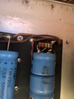
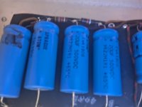
2.) the entire power supply was redone , Unknown power supply used with lots of extra wires, all electrolytics and some coupling caps replaced with Codes dating around '83 Mallory and Sprague atom. The reservoir caps look like 2 radials wired together in a way I have never seen before. 3 prong power cord was installed to replace 2 prong one with the green ground wire taped off. No ground. Ground switch still operational. Neg bias board rebuilt 100uf 75v cap, replaced diode, with two resistors added I have not seen before.
Here is what I have done so far. ( after initial inspection and startup tests. ), Amp operated ok , sounded a little louder than a stock one. with some crackle and background noise.
1.) Check initial voltages plate voltage 560 output tubes too high no current to speak of .
2.)cleaned pots, jacks, sockets. checked screen and grid resistors other cap values, did not find any out of tolerance or see any signs of damage or wear. . (some I will change anyway) not until I isolate the problem.
3.) Rewired three prong cord to chassis ground bypassing ground switch outlet and death cap.
check voltage , no change
4.)Replace 25uf 25v firecracker double electrolytic with new single ones. 4-5 , checked some more components, , check voltage --no change, replaced Bias cap checked resistors, No change in voltage but amp sounds considerably worse than it did. my concern is power supply is not right and has supply has been modified to accept it? (not sure). how do I check ?
I have run into similar issue before just not as severe. amp still sounded ok but needed bias - voltage adjustment or it was a bad pin 8 ground or bad screen resistor, Neg bias is -45v on this out of the adjuster pot. 15k resistor tests good.
I am now asking what I missed, ? the only measurement that was out of spec was the plate voltage and plate current, that I checked, Have not had one this way from the start in a while.
1🙂 the power transformer looks to be replaced. Brand and style I am unfamiliar with.
2.) the entire power supply was redone , Unknown power supply used with lots of extra wires, all electrolytics and some coupling caps replaced with Codes dating around '83 Mallory and Sprague atom. The reservoir caps look like 2 radials wired together in a way I have never seen before. 3 prong power cord was installed to replace 2 prong one with the green ground wire taped off. No ground. Ground switch still operational. Neg bias board rebuilt 100uf 75v cap, replaced diode, with two resistors added I have not seen before.
Here is what I have done so far. ( after initial inspection and startup tests. ), Amp operated ok , sounded a little louder than a stock one. with some crackle and background noise.
1.) Check initial voltages plate voltage 560 output tubes too high no current to speak of .
2.)cleaned pots, jacks, sockets. checked screen and grid resistors other cap values, did not find any out of tolerance or see any signs of damage or wear. . (some I will change anyway) not until I isolate the problem.
3.) Rewired three prong cord to chassis ground bypassing ground switch outlet and death cap.
check voltage , no change
4.)Replace 25uf 25v firecracker double electrolytic with new single ones. 4-5 , checked some more components, , check voltage --no change, replaced Bias cap checked resistors, No change in voltage but amp sounds considerably worse than it did. my concern is power supply is not right and has supply has been modified to accept it? (not sure). how do I check ?
I have run into similar issue before just not as severe. amp still sounded ok but needed bias - voltage adjustment or it was a bad pin 8 ground or bad screen resistor, Neg bias is -45v on this out of the adjuster pot. 15k resistor tests good.
I am now asking what I missed, ? the only measurement that was out of spec was the plate voltage and plate current, that I checked, Have not had one this way from the start in a while.
With a grid bias of -45V and screen voltage of 403V, the idle plate current should be significantly higher than 7mA.
Does the amp use good 6L6s?
How do you measure idle current?
Does the amp use good 6L6s?
How do you measure idle current?
Not grid bias voltage, but plate idle current I meant.
What about the 6L6s?
To be clear, I want to exclude bad or wrong power tubes (like EL34s).
What about the 6L6s?
To be clear, I want to exclude bad or wrong power tubes (like EL34s).
Last edited:
JJ matched 6L6GC Tubes tested good on tube tester. checked during start up and switched tubes from socket to socket, both of them are reading about the same on voltage measurements from pins, Grounds pin 8 passed continuity test but that is as far as I have gone.
There are different bias probes. Some need the DMM set to mA, others to mV.
Some measure plate current, others measure cathode current.
Not sure which type you have.
Did you measure plate voltages directly at tube pins?
If not, please do, but first remove the PI tube to avoid the risk of oscillation.
Some measure plate current, others measure cathode current.
Not sure which type you have.
Did you measure plate voltages directly at tube pins?
If not, please do, but first remove the PI tube to avoid the risk of oscillation.
when I turn down the bias adjustment pot the plate voltage goes down a total of 10 vdc the whole sweep of the pot and the current moves up from 0- 8 ma the whole sweep from1-10. I can get it around 552 at the lowest point. I have two different probes, they both measure milliamps , one has a attached box that has 2 displays for plate voltage and plate current in MA. the other connects to my multimeter and is supposed to be on the 200 ma setting and measures just plate current, I took measurements at the tune pins before I started , after each component replacement session. nothing has changed since we started that I have measured except it sounds worse with a guitar signal. the current fluctuates up around 5-7 milliamps when you play the notes.
Bassman bias with one tube? I found a tested working vintage Motorola 6LC GB tube (1) do not have another to check with. Installed it in both of the sockets by itself and was able to get current readings of 27 -29 Milliamps, which tells me the amp is working like it is supposed to if this were a measurement for 2 tubes I don't recall ever measuring with one tube only. I sometimes measure with no power tubes but usually individual measurements with all tubes installed. My question is what changes when only 1 tube is installed? I have to assume my 6l6GC tubes are bad even though the tester says they are good? The plate voltage is still 560 approx, both tubes are rated at 500 max (+,- 20%) ? would make in tolerance.
As late master repairman Enzo used to say: "A tube tester can tell you if a tube is bad but not if it's good".
These days they're selling tubes that don't conform to original datasheet specifications (in other words tubes that would have been scrapped by the manufacturer in the old days).
Nothing wrong with plugging a single tube only for plate idle current measurement.
High plate voltage certainly is no reason for low plate current.
Last edited:
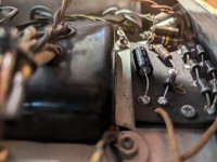
ok---what is the best way to test the filter caps ? looks like they were replaced sometime after 96 with sprague atom, I also have attached a pic of the bias eyelet board where it appears there arre two 100K resistoras stacked across the red transformer leads. ? I have never sween this on a Fender amp before and if it is I can not find it on the schematic. 2nd issue 2 reservoir caps are radial and I am unaware of how these are supoposed to work in this curcuit . If you have any advice as to leaving it or restoring it to what I think the schematic and layouts for these have. ?
Attachments
- Home
- Live Sound
- Instruments and Amps
- Fender BF Bassman AA864-AA165-AB165 help with plate voltage/ current issues.