Hello,
I have done a lot of research and hope to build an AA864 head. I re-drew the circuit (helped me to work through it) and have all the parts here or on the way to do everything on it. I tried to be complete; every wire/connection that I can think of is on there, it is what I would build from.
The only changes I made (that aren't accidental!) are using only the normal channel, tube rectification (5F6A style), adjusting the last dropping resistor for the lack of the other small signal tubes, and changing from a fixed mid-frequency resistor in the tone stack to a potentiometer.
I plan to start cutting holes this weekend. Do you see any mistakes?
Thank you for looking through it,
Bill
Attachments
If you are only building the one channel you won't need the 220k mixing resistor between V1b and the 500pF coupling cap - not that it would hurt to leave it in.
Thank you, I was wondering about that resistor. I wondered about its voltage divider effect with the following 1M grid resistor (it is easier for me to see/understand this effect in the circuit than its blending function with the bass channel).
Bill
Bill
I know the schematic calls for the 470R's; as I read I wondered if I needed a little more voltage drop at the screens, or just a bit more protection from them being potentially at or above the anode voltage in overdrive conditions. Not sure if it is a good idea or not.
So it really is just one 690R, I just already have a set of 470's and was adding.
So it really is just one 690R, I just already have a set of 470's and was adding.
You can use one 690R but I would recommend them to be 5 watt rating. However, if you got the 470R at 1 watt, then adding the 220R at 1 watt would give you 690R at 2 watts, that should be better than the 470R 1 watt resistors as per schematic.
You can use one 690R but I would recommend them to be 5 watt rating. However, if you got the 470R at 1 watt, then adding the 220R at 1 watt would give you 690R at 2 watts, that should be better than the 470R 1 watt resistors as per schematic.
How would wattage double when in series?
It won't double because they are not equal.
That said, just use a 470r but, as recommended, 5W .
You did a right thing: never ever build the "Bass instrument channel" which is plain horrible.
Even for Bass.
You don't need the mixing 220k .
That said, just use a 470r but, as recommended, 5W .
You did a right thing: never ever build the "Bass instrument channel" which is plain horrible.
Even for Bass.
You don't need the mixing 220k .
How would wattage double when in series?
What I meant was that 2 resistors at 1 watt in series or parallel gives you 2 watts of power dissipation. It doesn't necessarily mean that they will be dissipating the same amount of power as Fahey pointed out because they are unequal in value. Sorry for the confusion.
Thank you for all the comments, guys, and I understood what you were trying to say about about the wattage/power handling and will be going up on the screen resistors' power rating 🙂
Just back from Thanksgiving with family. 496 miles and only half way across Texas 🙂
Thanks again,
Bill
Just back from Thanksgiving with family. 496 miles and only half way across Texas 🙂
Thanks again,
Bill
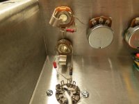
I am trying to wire two input jacks in typical Fender fashion with the Switchraft 12A's. I think my wiring shown is electrically correct, but worry that it might not be is nagging me.
I was hoping to get some fresh eyes to look at it and see if there is a mistake I am blind to.
The resistor on the bottom right is 68k CC, the bottom left 68k metal film (these going to pin 7), the upper 1M.
Thank you
I was hoping to get some fresh eyes to look at it and see if there is a mistake I am blind to.
The resistor on the bottom right is 68k CC, the bottom left 68k metal film (these going to pin 7), the upper 1M.
Thank you
Attachments

Hi Bill,
If you are going to build your amp, find the Fender Layout for your
AA864 amp. I saw that you have the schematic, there should be a
corresponding layout to go along with it.
Working from the layout will be a lot easier to build your amp from.
The Fender layouts are the exemplar of what a layout should look like.
That is they are the exemplary example. They'll show you exactly how
it should be wired up on what socket or to which lead etc.
It will save you countless hours of wondering.
Bill that pot doesn't look wired up correctly.
I've got some pics of of the Fender wiring that
should help you out, just about all the Fenders
were wired up the same.
If you have carbon films use them, they generally
sound better than metal films. Carbon comps are
alright too. The amp is going to be generating distortion,
a sterile metal film sound is not what you are going after.
Also vary the type of caps you use too. Some mylar,
some poly, some paper in oil, if you have any.
This will provide a rich and diverse sonic structure.
Have fun.
Cheers,
Last edited:
When I get a chance to find pics I'll post
some as I rebuilt the original. I think I have
two or three around here also that are in
the "queue".
some as I rebuilt the original. I think I have
two or three around here also that are in
the "queue".
I think I have a working amp. The only problem I had during testing was an initial positive feedback connection that was fixed by reversing leads on the primary of the OT.
It seems fairly quiet and without hum that I can hear on a cheap test-speaker.
I have attached my final schematic. The design voltages are in red, the measured voltages in blue in parentheses. I was hoping you would be willing to look at them and see what you think.
I was a little surprised that the filter choke didn't drop more voltage and I wonder about the readings at the anodes of the PI. I checked the 100k and 82k anode load resistors and, if labeled correctly, seem correct.
I am wondering if I need to add a resistor after the choke to drop 7-10 volts and/or do something about the phase inverter or whether I should leave well enough alone 🙂.
Thank you,
Bill
Attachments
What about the phase inverter? So the plate voltages are not the same exactly? Figure the current through each resistor, I get about 2ma and a fraction. Looks like about the same current through each side, so the voltages make sense.
What is the internal DC resistance of the choke? That will determine the voltage drop. I wouldn't expect it to drop much voltage.
I think I would have used single 560 ohm screen resistors rather than the two in series at each tube, but that doesn't really matter.
The question I'd ask is this: does it sound good? Does it operate as you'd like? If so, stop fixing it.
Thank you for replying.
Re. the PI, I understand that the anode resistors are different so that both phases balance in this style inverter. So, in operation, am I in balance as you suggest even though the reference schematic indicates differing voltages?
The choke's DCR isn't listed, but with only about 7mA through the small signal tubes plus the current through the screen, you are right, there won't be much voltage drop. I just wonder if I should drop another 10 volts or so before the preamp and PI tubes.
I could drop around 7 volts by just clipping out one of the parallel 2k resistors, I am just not sure I should. As you suggest it seems to be working good so I don't want to screw it up.
Thanks again,
Bill
- Status
- Not open for further replies.
- Home
- Live Sound
- Instruments and Amps
- Fender Bassman AA864 build