I purchased the complete F6 PCB boards, parts, and transformers etc.. from the DIYAudio Store. I have started stuffing the boards and immediately ran into some things I don't understand and I could use some help.
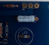
1) As far as I can tell the board for Channel A has a place for the 0.47 ohm R1 resistor but no place for the 0.56 ohm R2 resistor. And the Channel B has a place for the R2 resistor but no place for the R1 resistor. That makes no sense to me and isn't consistent with the schematic. A picture of the boards is attached.
Both boards contain an unlabeled position that is the right size for the resistor. Can anybody help me understand what is going on? Are my boards defective?
2) I am confused why there are both 5.1v Zeners and 6.0v Zeners. I have read that some people find one easier to bias than the other but Zenmod's schematic with 6.2v Zeners uses a 3.3K R7 and R8 resistor rather than the 10K resistors provided with the kit. Does it make a difference which Zener I use and if so which is better with the 10K resistors?
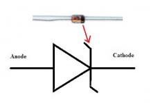
3) How do I orient the Zeners on the board? Obviously they are directional but I don't know enough about them or the schematic symbol to know how they should go. There is a dark band on one end of the Zener. does that go at the base of the triangle or the tip of the triangle on the board?
Thanks.
Paul
1) As far as I can tell the board for Channel A has a place for the 0.47 ohm R1 resistor but no place for the 0.56 ohm R2 resistor. And the Channel B has a place for the R2 resistor but no place for the R1 resistor. That makes no sense to me and isn't consistent with the schematic. A picture of the boards is attached.
An externally hosted image should be here but it was not working when we last tested it.
Both boards contain an unlabeled position that is the right size for the resistor. Can anybody help me understand what is going on? Are my boards defective?
2) I am confused why there are both 5.1v Zeners and 6.0v Zeners. I have read that some people find one easier to bias than the other but Zenmod's schematic with 6.2v Zeners uses a 3.3K R7 and R8 resistor rather than the 10K resistors provided with the kit. Does it make a difference which Zener I use and if so which is better with the 10K resistors?
3) How do I orient the Zeners on the board? Obviously they are directional but I don't know enough about them or the schematic symbol to know how they should go. There is a dark band on one end of the Zener. does that go at the base of the triangle or the tip of the triangle on the board?
Thanks.
Paul
I may have inadvertently broken the link to the picture of the boards. Hopefully this works.
An externally hosted image should be here but it was not working when we last tested it.
Hi Paul,
no, we don't see your pictures.
I try to answer some of your questions:
1)
Your pcbs should look like these in the build guide:
F6 Illustrated Build Guide
So they are not more faulty than those.
2) Use the 6.2V Zeners. See linked post above, explained there.
If you have, use 3.3k Resistors, not 10k.
3) Yes. Look at the pictures of the build guides. Maybe you can identify the orientation on some pictures.
Place the components, that you can read the value from above. Dbugging is easier this way.
Best,
Ulf
OK, so you are saying that I should just assume that the unlabeled spots for the resistors are the place where the R1 or R2 go depending on the Channel? Is there a reason why those are the only unlabeled spots on the board?
I did look at those pictures of the diodes but the resolution is low enough that it is difficult to make out which end of the diode has the band but after looking at a bunch of pictures it appears the banded end goes at the point of the triangle not the base right?
I did look at those pictures of the diodes but the resolution is low enough that it is difficult to make out which end of the diode has the band but after looking at a bunch of pictures it appears the banded end goes at the point of the triangle not the base right?

Thanks. Have you ever run into an explanation of why those places on the PCB aren't marked? I did search through the build guide without finding anything helpful but it is so large I might have missed it.
FYI. F6 BOM I used:
R1 0.56ohm 3W
R2 0.47ohm 3W
R3 100ohm 3W
R4 18ohm
R5 1K
R6 47K
R7,8 3K3
R9,10 10K
R11,12 120ohm
R13 15K
P1,2 5Kohm Bourns 3386W or 3296
C1,2 1000uF 25V
Q1,2 IRFP240 (no need match)
Q2 2SK170BL (Q2,Q3 need match Idss)
Q3 2SJ74BL
Z1,2 1N4735 (6.2V)
T1 Jensen JT-123-FLPCH
---
For Zener diode direction, the side has a black line is cathode side. Check the datasheet for your Zener
Attachments
Last edited:
The lack of the resistor markings on the PCBs is a completely planned, intentional and cunning intelligence test, placed there by the global Illuminati many years ago much to the surprise of everyone. You will be contacted soon by the brotherhood since you seem to have devised the answer.
🙂 🙂 🙂
...Or it just never got marked and forgotten about.
The extra zener diodes are included so you can increase the bias voltage if required. Start with the lower value one and change if you can’t get enough bias. As previously mentioned, the black line goes over the funny ‘Z’ line on the diagram.
Thanks 6L6. I already wired the 6.0v zeners in. I'm about to install and test my first channel so I hope using the 6.0v zener won't cause anything to fail.
I suspect you aren't the right person for this input but it would have saved me about 20 minutes of eye strain and uncertainty if the two types of zener were seperated. Even with the magnifier on my phone I found it quite difficult to figure out which was which.
I suspect you aren't the right person for this input but it would have saved me about 20 minutes of eye strain and uncertainty if the two types of zener were seperated. Even with the magnifier on my phone I found it quite difficult to figure out which was which.
This is the best $13 you can spend in all of DIY -
https://www.amazon.com/dp/B07WT9VVZB/ref=cm_sw_em_r_mt_dp_1HWFDYWYVJRJVJJ6AJ1V
Tests essentially anything. Transistor, resistor, capacitor, diode, choke, et.all.
https://www.amazon.com/dp/B07WT9VVZB/ref=cm_sw_em_r_mt_dp_1HWFDYWYVJRJVJJ6AJ1V
Tests essentially anything. Transistor, resistor, capacitor, diode, choke, et.all.
I have completed my F6 PSU which tests great. I hooked up the first Channel A amplifier board. Powered on with Dim Bulb Tester and everything is great. Hooked to the mains and powered on and everything still looks great. Bias is about 0.72, Offset is close to 0, temperature at pin 2 of the mosfet is about 49 degrees C and heatsink is about 44 degrees.
So everything looks great and seems to be working fine but the LED doesn't light. My kit from the DIY Store included red LEDs. The R13 resistor is 15K and tests fine. When I hook up my Multimeter with the red lead on the side of the LED connected to the resistor and the black on the other side it lights up and reads 1.8V which seems correct though I'm just guessing at that. So assuming I understood all the schematics and data on the LED, i.e. connection long lead/anode to the resistor and the short lead/cathode to ground then the LED ought to be wired correctly.
Any thoughts about why the LED doesn't light? Am I misunderstanding what all these readings mean? And most importantly, should I even care about it lighting or not lighting?
Yes, I know that is usually the problem but it isn't a simple fix because of how I have the wires set up. It would be a very time consuming fix. That is why I asked if I should even care about whether or not the LED lights up. Does the LED play any role in the circuit besides indicating that the board is receiving power? If not I'll just leave it alone.
Also, if I understand how the multimeter works when it is testing a diode it isn't installed backwards, but I may not understand how the multimeter works but I would have thought the red lead was the + Anode side and if so the LED isn't backwards
Also, if I understand how the multimeter works when it is testing a diode it isn't installed backwards, but I may not understand how the multimeter works but I would have thought the red lead was the + Anode side and if so the LED isn't backwards
The LED does not pay a role in the circuit. Also on one of the boards (can't remember which)
it's actually on the negative rail.
it's actually on the negative rail.
Does the LED play any role in the circuit besides indicating that the board is receiving power?
No.
Best,
Anand.
OK, so you are saying that I should just assume that the unlabeled spots for the resistors are the place where the R1 or R2 go depending on the Channel? Is there a reason why those are the only unlabeled spots on the board?
I did look at those pictures of the diodes but the resolution is low enough that it is difficult to make out which end of the diode has the band but after looking at a bunch of pictures it appears the banded end goes at the point of the triangle not the base right?
Simply human mistake forgot the silk print when drawing the PCB 😛
Or it's an interesting challenge for DIYers - forcing you to read the circuit or ask in the forum and having DIY fun.
I did not even noticed this when I built my F6.
Some of these "interesting challenges" feel more like hazing than puzzle solving LOL.
I've completed the F6. I've been playing it for the last 3 hours and it sounds spectacular. I had high hopes for the F6, but I was also pretty skeptical that such a simple design would really perform well. So far I am very happy and if it improves with burn in that will upgrade to ecstatic. Great detail, very precise while still being exceptionally musical and involving. Bass is strong and tight. Soundstage is wide but a little more two dimensional than my Willsenton R8 tube amp. The F6 makes my Tekton Moabs sound a little more like my Magnepan 3.7s while retaining the dense, rich, involving quality of the Moabs and that is a very good thing.
To be on the safe side, I set the bias to 0.825 volts and the offset was fluctuating around +- 2 mv. After running the amp for 3 hours the hottest part of the external heatsink is 48 degrees C. So that seems inline with the guidelines in the build guide.
Two questions that I wasn't able to find answers to searching. First, are there any positives or negatives from setting the bias higher and running hotter, possibly with a small fan? Does the sound quality get better or worse with a higher or lower bias?
Secondly, there is a low hum audible from a foot or two of the speakers but not at the listening position. Is that hum because the offset has drifted? Or could it be because I didn't do a very good job with my wire management and I'm picking up some interference inside the chassis?
-generally, greater Iq, better sound; but - taking care of both temperature and figure of dissipation per device ( with which you're content; flawless heatsinking and 50W as figure for IRFP150; IRFP240 say no more than 40W)
-DC offset not having anything with hum; normal range is +/-100mV as general rule, but even more is no problem , if there is no abrupt changes
-DC offset not having anything with hum; normal range is +/-100mV as general rule, but even more is no problem , if there is no abrupt changes
Not an engineer so struggling with some of these concepts.
Iq = quiescent current = bias voltage? So all things being equal, if temperature is controlled and wattage which I believe is calculated as (bias/0.47)*rail voltage is<=40 watts then it should be good and sound quality will be optimal?
If so then it seems I may have stumbled onto the optimal bias for my build?
Iq is quiescent current, while bias voltage is what is controlling device , having that Iq
Often we all are saying bias, while thinking of its consequence - Iq ........ which is not good, confusing Greenhorns 🙂
dissipation per device is Iq through that device, multiplied wit voltage across the same
usually easiest devised as sum dissipation, divided with number of outputs
Iq at device being measured as voltage across source resistor, then divided with value of same resistor
example for F6 - say 1A6 Iq, rails (2 x 22V5), so sum dissipation being 1A6 x 45= 72W
divided by 2 = 36W per device
apply to your exact numbers and that's it
- Home
- Amplifiers
- Pass Labs
- F6 Build Questions