Hi all,
New to the Forum. Trying to finish this F5 build and I seem to have hit a wall and need to seek expert help! I had everything hooked up and was going through the steps in initial start-up and my fuse blew. I began disconnecting the boards from the power supply board and it still shorted out. Next I tried disconnecting one side of the ps board from its rectifier and no short. I swapped sides and still no short, but when I hooked them both up again (to the opposite side rectifier) the fuse went again... ?
So it seems that as long as I only have one side (no matter whichever side) of the PS board hooked up it is fine. But when I connect both left and right I get a Short.
I'm attaching some photos. Any help of advice on where to start troubleshooting would be greatly appreciated! Thanks
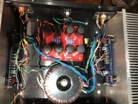
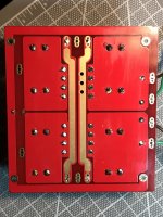
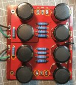
Attached are some photos of my F5 and Power supply board...
Attachments
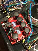
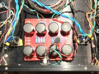

Sounds like a possible short between left / right on the filter board.
looking at the last two photos of the filter board, it looks like you might have possible solder 'bridges' shorting across too adjacent tracks.
So I'd start with a really good, close, well lit inspection, desolder, and resolder of the filter board.
Edit;
See pic, yellow circles, some of those look like they may be shorting to other tracks.
Edit 2.
I also notice in the two strings of four resistors, that each string seems to have a single resistor with a different value, Is that correct for that board ?
So maybe double check the resistor values.
Attachments
Last edited:
build and use a Mains Bulb Tester (MBT).
Use the tester to to check the wiring on each stage as your build progresses.
test the transformer wiring.
test the transformer+rectifier wiring.
test the transformer+rectifier+smoothing cap wiring.
test the transformer+rectifier+smoothing+amp cap wiring.
etc.
Use the MBT every time you modify anything in your build.
I don't like the big loop in the power thermistor wiring.
Can you rearrange the mains wires to minimise loop area?
I don't like the unbypassed Power Thermistor.
It increases the power supply impedance.
Consider adding a bypassing relay on a time delay. Since you have a Thermistor you can use a longer delay. Try 10seconds.
Can you rearrange the mains wires to minimise loop area?
I don't like the unbypassed Power Thermistor.
It increases the power supply impedance.
Consider adding a bypassing relay on a time delay. Since you have a Thermistor you can use a longer delay. Try 10seconds.
Looks like one of your snubber caps on the rectifier diodes may be shorting against the case. Take out the snubbbers.
Lots of problems around here with that jims audio psu board. Do a search. Could be the issue.
Also, use a bulb tester for sure. Test in segments (transformer, transformer + psu, then boards)
You sure you have zeroed the bias on BOTH boards? You sure the mosfets are isolated?
Lots of problems around here with that jims audio psu board. Do a search. Could be the issue.
Also, use a bulb tester for sure. Test in segments (transformer, transformer + psu, then boards)
You sure you have zeroed the bias on BOTH boards? You sure the mosfets are isolated?
Hello everyone and thanks for all the great advice! Read on, this story has a happy ending 🙂
OldNCranky- thank you for taking such a close look at my beginner soldering work. With the help of a jewelers loup and pright light I went over every joint and cleaned up everything. That last resistor on each side of the 4 sets is just from a different package so the bands are slightly off. They are all .47 ohm. After a careful inspection I hooked everything up and using a mains bulb tester (Thanks AndrewT, these fuses can get pricey!)... my short is still there.
So I decided to start from the start! What could I have messed up in my haste and excitement to get this baby running?! So Decide to measure my transformer secondaries and sure enough I had twisted the wrong pairs together! Swapped them and am now reading 25v on each side of the filter board! Whooo Hoo!!
AndrewT- in terms of the thermistor, could I just bypass it with a manual switch a few seconds after I power on?
Hikari- thanks for pointing out the Snubbers. In testing for the "short" I disconnected them, but obviously that were not my problem 😛
What is the conscious on Snubber caps for the F5? Leave them in or take them out?
Thanks!
Arnie
What is the conscious on Snubber caps for the F5? Leave them in or take them out?
Thanks!
Arnie
That is an extra mains switch !AndrewT- in terms of the thermistor, could I just bypass it with a manual switch a few seconds after I power on?
The snubbers are for the transformer to rectifier and how they interact.Hikari- thanks for pointing out the Snubbers. In testing for the "short" I disconnected them, but obviously that were not my problem 😛
What is the conscious on Snubber caps for the F5? Leave them in or take them out?
Thanks!
Arnie
- Status
- Not open for further replies.
- Home
- Amplifiers
- Pass Labs
- F5 Power Supply Short- MYSTERY!?