I'm speaking without knowledge here, but the capacitors that Nelson uses for the raw ps in his F5 strike me as very small. Is that because it's a Class A amp at low power where average current doesn't change? Seems that once it began operating in Class AB mode, ps voltage would start to swing around a bit. Is that not true?
If so, would larger caps help? Any downside to that?
If so, would larger caps help? Any downside to that?
Nelson's design is 60,000uF per rail for the F5.
For 25 Watts Class A into a load that can go down to 1 ohm without misbehaving as Nelson so eloquently puts it, means the PSU is more than adequate.
Nelson has always been known to have beefy PSU's in all his amps.
It will not hurt at all to build your own F5 with more capacitance, mine has 100,000uF per rail and sounds so powerful and in control at all times.
Cheers
Gary..
The caps don't have to be as large on Class A amps because they have a bias current and so the average current doesn't really change much?
Depends on how you look at it. The large quiescent current creates
large ripple so you see more supply issues there. On the other hand,
these same supply issues arise under high power conditions with
Class B or AB.
This is DIY however, and over-the-top capacitance is part of the
landscape because it's not that expensive and there is little
controversy over the benefits, especially CLC or CRC.
😎
I've got an F5, 0.61v bias
PSU 60,000 uF per rail. 500KVA 18V transformer. DiyAudio PCBs V2
Yesterday I put the scope on the PSU DC out and discovered I've ~290 mV of quiescent ripple.. yuK!
Played some music, boy did it look ugly.
The filtering caps are 15,000 uF Nichicon 50v GY(m) series
So I placed 1 more of the same cap on each rail output, this dropped the quiescent ripple down to ~190mV per rail.
So now each rail has 75,000 uF.
The amp sounded different, it was now more pronounced in the lower registers.
My question is, as the CRC circuit is no longer balanced across the "R" component when the 15,000 uF caps are on rail outputs, can I expect the impact on sound to be similar if I was to retain balance across the "R" component with the additional capacitance ie. instead change out all 8 capacitors to a higher value. My aim is to resolve the excessive ripple without to much impact on sound
Also, can I move these 2 additional capacitors over to the DC in on the PCB to see what effect this has? I'm just not sure if the bleeder resistor will pose a problem doing this?
Thanks Allan
You are just seeing the normal expected behavior of a capacitor. The first C bank directly relates
to the ripple peak to peak voltage for the chosen DC bias current.
If I is the DC bias current, and the capacitor behavior is I = C * dV/dt, the ripple voltage per charging period
is: dV/dt = I / C. So with a higher bias I -> more ripple, and for a higher C -> less ripple.
The series R and the second C bank then filter the ripple voltage to make a more pure DC voltage.
The R is not strictly necessary, but it will lower the noise level in conjunction with the second C bank.
The second C bank will have a more direct effect on the sound than the first bank, because of the R.
The two C banks don't need to be equal. Choose the first bank for the ripple voltage desired.
Last edited:
thanks Rayma. ok so adding the extra caps on the first C bank should be the better option to drop the ripple, I'll give that a go then. Thanks
I did think of PSUD2 but it isn't an option for me.. I run a Mac
I did think of PSUD2 but it isn't an option for me.. I run a Mac
Yes, definitely. The second C bank will have much less effect on the ripple seen at the rectifier output.
At some point there could be inrush current problems that will need to be addressed with a thermistor, etc.
At some point there could be inrush current problems that will need to be addressed with a thermistor, etc.
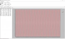
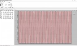
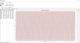
I had a few PSUD models saved from when i built mine, punched in your cap sizes and took a few screen shots for you, numbers are close enough to your measurements. The last one is with a Hammond 159ZJ chokes.I've got an F5, 0.61v bias
PSU 60,000 uF per rail. 500KVA 18V transformer. DiyAudio PCBs V2
Yesterday I put the scope on the PSU DC out and discovered I've ~290 mV of quiescent ripple.. yuK!
Played some music, boy did it look ugly.
The filtering caps are 15,000 uF Nichicon 50v GY(m) series
So I placed 1 more of the same cap on each rail output, this dropped the quiescent ripple down to ~190mV per rail.
So now each rail has 75,000 uF.
The amp sounded different, it was now more pronounced in the lower registers.
My question is, as the CRC circuit is no longer balanced across the "R" component when the 15,000 uF caps are on rail outputs, can I expect the impact on sound to be similar if I was to retain balance across the "R" component with the additional capacitance ie. instead change out all 8 capacitors to a higher value. My aim is to resolve the excessive ripple without to much impact on sound
Also, can I move these 2 additional capacitors over to the DC in on the PCB to see what effect this has? I'm just not sure if the bleeder resistor will pose a problem doing this?
Thanks Allan
Attachments

^ what he said. Putting the extra cap on the output side does almost nothing, only knocks off a few mv of ripple.Yes, definitely. The second C bank will have much less effect on the ripple seen at the rectifier output.
At some point there could be inrush current problems that will need to be addressed with a thermistor, etc.
Yes, there won't be much effect on the rectifier ripple, but it will still improve the sound in some cases.^ what he said. Putting the extra cap on the output side does almost nothing, only knocks off a few mv of ripple.
There is a version for the Mac, which I have used.I did think of PSUD2 but it isn't an option for me.. I run a Mac
https://www.diyaudio.com/community/threads/psud2-for-mac-released.350100/
thanks for that McandMar, pretty close alright, only 20 odd mV out.. I need to get myself up & running with that PSUD2.
Hey could you run it again for me please with 88,000 uF capacitance per rail? Thats what I intend going up too so be good to see before I buy.
Thanks for the link RayMa.. will grab a copy. I'm using a thermistor & so far no inrush issue.
Well I moved the temporary caps from the second bank to the first. I got pretty much the same result for ripple, down from ~290 to ~190mV though it definitely didn't emphases the lower registers as much and I think in comparison they're better defined.
Appreciate the help gents
Sorry for dragging this somewhat off topic but I have been trying to get a handle on PSUD for a while now to simulate a CRCRC PS. Im sure I am messing something up in the transformer or current settings. Can you share the parameters you placed for the transformer, (nominal V and A, and primary V and offload V) and also the current source settings (stepped or constant and values). I am going to try and replicate your simulation and try an figure out where my errors lie. Lastly is the 1N5822 the actual bridge you used or just close enough? Ive been trying the GBPC3504. Thanks for any help, it just feels like I have one setting off which is leading to garbage data.
- Home
- Amplifiers
- Pass Labs
- F5 Power Supply Caps Seem Small