Howdy,
I just finished wiring up my first F5 build, and started to bias it and ran into a some issues/questions.
I'm using diyaudio store boards and matched jfets. IRFP9240 and IRFP240 mosfets.
So, I connect 3 DMM's per the build guide.
One connected across R11, one connected across R12, and the third across that channel's binding posts.
I turn the pots counter-clockwise until they click, presumably that means they're all the way 'down'. Then plug the amp in and start the bias procedure.
As soon as I turn on the amp the first two DMM's both read ~.067mv, and the offset is right about .006mv.
As I adjust the two pots, if I zero out the offset(binding posts) the readings are all about the same variation apart from each other. I can't seem to get it to bias up to the first stage of ~.4mv with a zero offset. If I get R11, and R12 to ~.4mv then the offset is very nearly the same.
So after awhile of fiddling with that channel, I turned the pots counter-clockwise until they clicked, powered down the amp and connect all the DMM's to the other channel.
Fired it up went through the same steps and the results are the same.
I'm not sure if I'm not turning the pots enough, or if I'm missing something obvious, or what.
Any guidance, tips, etc. would be greatly appreciated.
Thanks~
Gable
If they are the normal 25 turn pots you may have to turn them a lot to get a result.
Are you using a bulb tester?
You should be for initial trials, then remove it when you are stable at about 3/4 bias.
If you are using store boards marked F5 V3.0 you should be measuring bias across R6 and R7 0.47r 3w resistors.
Are you using the correct circuit diagram? CHECK!
V3 is different to the early one in the article!
This is the circuit for V3 boards.
https://cdn.shopify.com/s/files/1/1006/5046/files/F5_Schematic_w-P3.jpg
Last edited:
If they are the normal 25 turn pots you may have to turn them a lot to get a result.
Are you using a bulb tester?
You should be for initial trials, then remove it when you are stable at about 3/4 bias.
If you are using store boards marked F5 V3.0 you should be measuring bias across R6 and R7 0.47r 3w resistors.
Are you using the correct circuit diagram? CHECK!
V3 is different to the early one in the article!
This is the circuit for V3 boards.
https://cdn.shopify.com/s/files/1/1006/5046/files/F5_Schematic_w-P3.jpg
R7 and R8?
R6 is a 2.21k 1/4w on the schematic and my boards.
I do have the F5 v3 boards. Thank you for the bias location correction.
Am I to short the inputs during biasing as well?
Thank you ~
Gable
If they are the normal 25 turn pots you may have to turn them a lot to get a result.
Are you using a bulb tester?
You should be for initial trials, then remove it when you are stable at about 3/4 bias.
If you are using store boards marked F5 V3.0 you should be measuring bias across R6 and R7 0.47r 3w resistors.
Are you using the correct circuit diagram? CHECK!
V3 is different to the early one in the article!
This is the circuit for V3 boards.
https://cdn.shopify.com/s/files/1/1006/5046/files/F5_Schematic_w-P3.jpg
Just set the bias on my right channel, ~.4v and ~.001 offset across the binding posts.
I'll let it stabilize then do the left channel.
Thank you for the tips!
R7 and R8?
R6 is a 2.21k 1/4w on the schematic and my boards.
I do have the F5 v3 boards. Thank you for the bias location correction.
Am I to short the inputs during biasing as well?
Thank you ~
Gable
Stop!
If you have V3 boards go back and check your build against the V3 schematic.
You would not be the first person to mix them up.
The bom also relates to the early version, not V3.
Let us know then.🙂
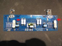
You should be checking the two resistors marked which should be 0.47r 3w.
Attachments
Stop!
If you have V3 boards go back and check your build against the V3 schematic.
You would not be the first person to mix them up.
The bom also relates to the early version, not V3.
Let us know then.🙂
You should be checking the two resistors marked which should be 0.47r 3w.
Yep, that's what I'm checking. They are 3w .47ohm 😀
- Status
- Not open for further replies.
- Home
- Amplifiers
- Pass Labs
- F5 bias issues - newb build