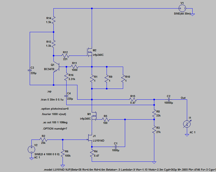
2 circuits based on F3 design.
The first one is Zero Feedback and gives excellent performance but highish output impedance (11 Ohms if I am not mistaken).

The second one is the one that interests me most but what are my options for lowering output impedance without adding feedback?
The brain is having a melt down.
The first one is Zero Feedback and gives excellent performance but highish output impedance (11 Ohms if I am not mistaken).
The second one is the one that interests me most but what are my options for lowering output impedance without adding feedback?
The brain is having a melt down.
Ok going to build this one first. Don't need much gain anyway so this will do the job.
Might even drop the drain resistance to 3 Ohms.
The finished amp will look a little different to this but this is good enough to get the idea of what I am building.
Might even drop the drain resistance to 3 Ohms.
The finished amp will look a little different to this but this is good enough to get the idea of what I am building.
An externally hosted image should be here but it was not working when we last tested it.
just take care of LU temperature
I've got quite a few that I can destroy. Hahahaha
Is 60 degrees ok?


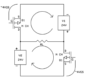
While I am at it I may as well build this Circlotron circuit.

Looks like a bridged amp with 2 power supplies, not circlotron. 😉
Check out the "new-tron Isotope 1" or something like that. A Grey Rollins creation.
Last edited:
Looks like a bridged amp with 2 power supplies, not circlotron. 😉
Check out the "new-tron Isotope 1" or something like that. A Grey Rollins creation.
Looks like you are correct. It appears to current clip.
I built a circlotron many years ago, source follower though, it worked perfectly after some time messing around with it.
I referenced Mike Rothacher's basic circuit. Does this mean it is incorrect?
I'm a bit rusty, been riding motorbikes and haven't touched audio for a few years.
I used your lu1014d model, are you happy enough with it to believe the simulations.
Last edited:
You have a good eye.Except for the P ch symbol that has N next to it 😀
Hahahaha
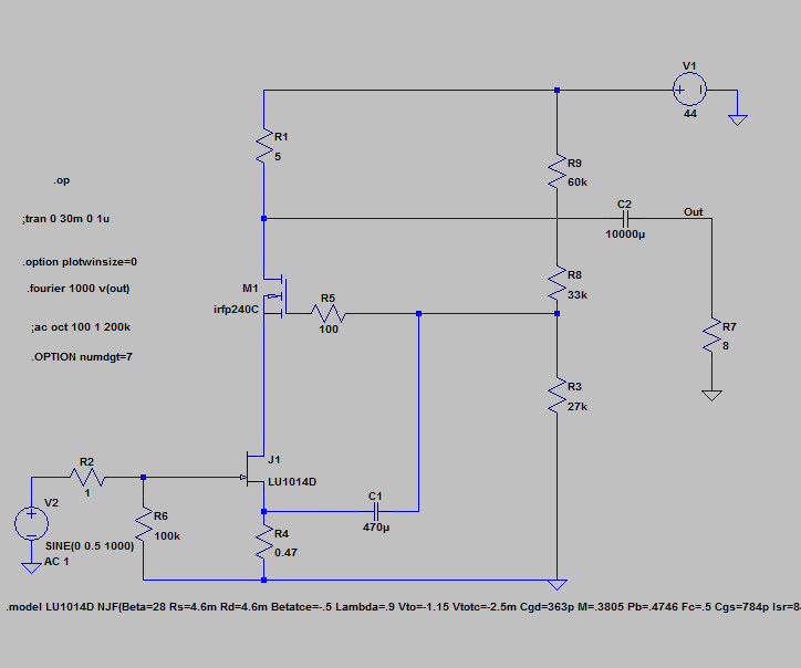
This one is dedicated to Zen Mod
The Choke loaded version.
Extremely good performance from a simple circuit. The choke is 30H with a series resistance of 5 Ohms. Hopefully that won't be too difficult to either purchase or build. Might be able to reduce inductance some to get the 5 Ohm DC resistance value. I'm totally inexperienced when it comes to building chokes
Lu1014d is at 11 Watts dissipation (Rated as a 69W part) hopefully 11Watts is ok. Either way I can easily reduce it if needed.
Here is the distortion at 1W rms. Fairly impressive. A lot to like here.
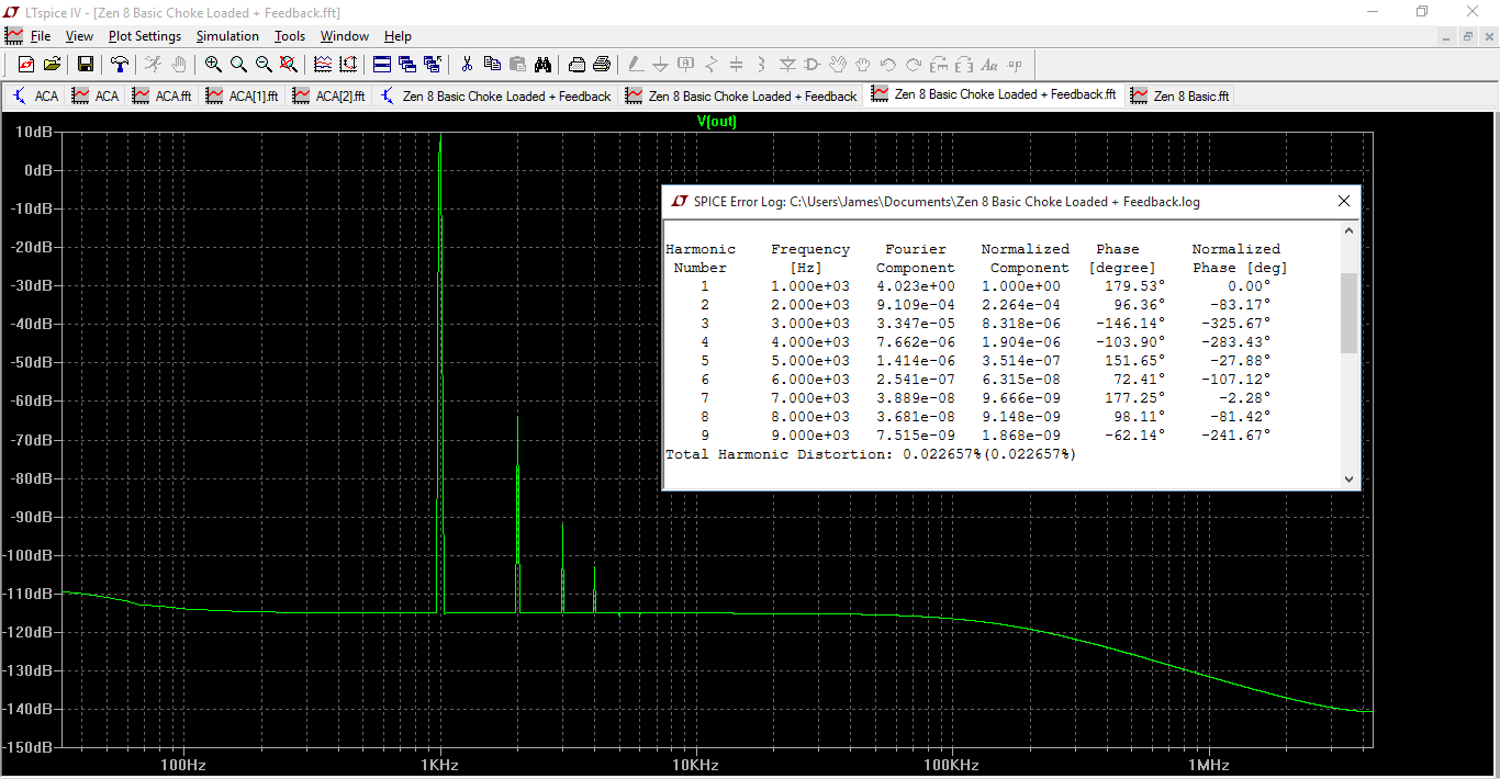
I don't need a lot of gain so that is why I chose those feedback values but if you need more gain, R2 can be changed to 9k and R6 to 50k

The Choke loaded version.
Extremely good performance from a simple circuit. The choke is 30H with a series resistance of 5 Ohms. Hopefully that won't be too difficult to either purchase or build. Might be able to reduce inductance some to get the 5 Ohm DC resistance value. I'm totally inexperienced when it comes to building chokes
Lu1014d is at 11 Watts dissipation (Rated as a 69W part) hopefully 11Watts is ok. Either way I can easily reduce it if needed.
Here is the distortion at 1W rms. Fairly impressive. A lot to like here.
I don't need a lot of gain so that is why I chose those feedback values but if you need more gain, R2 can be changed to 9k and R6 to 50k
Last edited:
have some PP iterations here , also tried on my reference MDF table
usual FW mumbojumbo**
**what you see is what you get
also , there is Magura's pair of Killer monoblocks
usual FW mumbojumbo**
**what you see is what you get
also , there is Magura's pair of Killer monoblocks
Must have been smoking some of Dutchies finest product, 2H is more than adequate on the inductor.
- Status
- Not open for further replies.
- Home
- Amplifiers
- Pass Labs
- F3/SIT Variations