Repairing this amp over here: https://amp-performance.de/en/453-Eyebrid-1Y2000D.html
It has been butchered badly from previous repair attempts.
I'm missing Q4 and Q6....I found another thread here that says Q6 is J108, but not sure this is true.
ZD1 also have been swapped and messed around,
I've tried looking up everywhere online if there is high quality picture whereby i can read the transistor markings but with no avail.
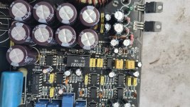
i am working on an Eyebrid 1Y2000D monoamp.there is missing one transistor.you can see it on the photo.it is Q6
the transistor Q3 is a MPSA56.
does anybody know what Q6 (in the red circle) is?
the transistor Q3 is a MPSA56.
does anybody know what Q6 (in the red circle) is?
Attachments
Q4 still a mistery. But for Q6.
I don't have any J108 JFET this one seems to be obsolete, can I use the J112 ?
According to ChatGPT I cannot:

I don't have any J108 JFET this one seems to be obsolete, can I use the J112 ?
According to ChatGPT I cannot:
Is the J109 available?
Those JFETs are typically used for muting and if used in that way won't be critical to be in the circuit for general troubleshooting.
The voltages on the various pads for Q4 may help find a suitable sub.
Those JFETs are typically used for muting and if used in that way won't be critical to be in the circuit for general troubleshooting.
The voltages on the various pads for Q4 may help find a suitable sub.
Is the J109 available? = yes, i can source it.
Q4 may help find a suitable sub. = I'm afraid to put voltage to the amp before fitting anything to Q4 and also zd1 was changed before and I don't know the correct zener voltage value.
Q4 may help find a suitable sub. = I'm afraid to put voltage to the amp before fitting anything to Q4 and also zd1 was changed before and I don't know the correct zener voltage value.
Fitted J109.
Amp starts and plays just fine, but the relays don't engage. There are two of them 6v ones, but wired in series, so 12v in total.
They are being driven/pulled to ground by a NPN 2SD669.
Emitter is connected to GND.
Collector is connected to the relay = 11.8v
Base = 0.45v it's actually connected thru 2 resistors in series (10k total resistance) to pin 2 of the missing Q4.
Q4 voltages are referenced to GND:
pin 1 = 0 connects to GND thru 10k resistor
pin 2 = 0.45v connects thru 10k resistors to base on the 2SD669
pin 3 = 12.3v from Q3
I've tested the relays outside of the board, they work just fine. Voltage across their contact/engage points is 0v, so they are not being engaged at all, i think due to the missing Q4 transistor.
For anyone looking for this information - Q4 is PNP, i've used MPSA56.
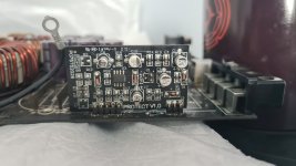
Now that did not help a lot since protect board is also a part of the relay schematic and in my case Q1 was totally dead. Transistor is G1 - MMBT5551.
Now i do have some voltage across the relays but it's not high enough...it's way too low.
I think this is due to the changed ZD1 Zener with a wrong voltage value as this one is connected to Q3 which is connected to Q4, and Q4 actually controls NPN 2SD669. I'll have to experiment with some different zener values.
This all would have been much more easier and faster if the previous "tech" would have not done what he did....
Attachments
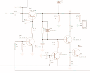
The polarity (from the voltages you posted) looks wrong for a PNP with the pin configuration of that transistor.
Q4 voltages are referenced to GND:
So this is not correct below
pin 1 = 0 connects to GND thru 10k resistor = Emitter of PNP
pin 2 = 0.45v connects thru 10k resistors to base on the 2SD669 = Base of PNP
pin 3 = 12.3v from Q3 = Collector of PNP
Should be a NPN like MPSA42 ?
So this is not correct below
pin 1 = 0 connects to GND thru 10k resistor = Emitter of PNP
pin 2 = 0.45v connects thru 10k resistors to base on the 2SD669 = Base of PNP
pin 3 = 12.3v from Q3 = Collector of PNP
Should be a NPN like MPSA42 ?
I think so but there is a problem with the base voltage (if it's an AO6 or an A42). 0.45 would be marginal to make it conduct. The diagram I posted was the only thing that I could find that was remotely the same.
The A42 is typically used for high voltage circuits. It's a good general purpose transistor so there really isn't a good reason to use the A06. It was what came to mind first.
The A42 is typically used for high voltage circuits. It's a good general purpose transistor so there really isn't a good reason to use the A06. It was what came to mind first.

" 0.45 would be marginal to make it conduct." = exactly, I would expect 0.55~0.6v. I will experiment a bit more as the amplifier is already working perfectly fine, just the relay part needs some attention and I'm not fan of bypassing the relays...
A note for others reading this. The base voltage (assuming that the emitter is grounded) isn't fed a precise voltage (like the common 0.6v that's given for the base-emitter voltage). It's driven through a voltage-dropping resistor that allows the base voltage to be whatever that transistor determines it to be. As an example, a 1k resistor may be driven with 10v and the resistor will have 9.4v across it. If driven with 5v, the resistor would have 4.4v across it.
I've changed the Q4 voltages for MPSA42.
Changed the Relays too (just to be sure).
Something has changed.
Now Q4 with the MPSA42 in place voltages are:
Emitter = pin 1 = 0 connects to GND thru 10k resistor
Base = pin 2 = 0.05v connects thru 10k resistors to base on the 2SD669 and also to one of the pins of the small driver board where I had replace the shorted MMBT5551 (tied to this pin thru a diode) - now I don't have that 0.45v any more, just 0.05v
Collector = pin 3 = 12.3v from Q3
ZD1 has 14.5v аcross it, I suppose it's a 15v zener, but who knows if this should be the case.
If I forcefully short the collector of the 2SD669 to ground - relay engages....So the base of that 2SD669 transistor needs over 0.5v-0.6v volts in order to transistor to work, so the emitter can pull the collector to ground and relay to engage. Only issue is that somewhere instead of the 0.5-0.6 volts....i do get now 0.05v.
It's hard/complex without schematic as this point connects to the PS board, to Protect board, to some other transistor and part of the main board....this the board is black and nightmare to trace anything....
It's hard/complex without schematic as this point connects to the PS board, to Protect board, to some other transistor and part of the main board....this the board is black and nightmare to trace anything....
I know you said the diagram I posted wasn't close but is there possibly a transistor that corresponds to Q3? That transistor would be used to prevent the relays from engaging. It would be used for protection or for the initial mute delay.
This is my line of thinking too. As this 2SD669 connects to various parts of the amplifier I've checked the PS driver board, the Protect board and also the part whereby we have had the missing transistors Q4 and Q6=J108 (which we swapped to J109 as J108 is obsolete) but nothing else is shorted, burned, open or give me any odd readings.
The amp does not go into protect, there is green light, produces output, etc, so it's just the part with the relay engagement. Even if it's a leaking transistor without a schematic I would not know where " corresponds to Q3? " would be located.
I may re-check the Protect board once again as Q1 being there shorted it may have cause some other damage too, but i cannot see anything wrong or odd at the DMM,
EDIT: It's not the Protect Board, I fitted brand new transistors over there and check the resistors if they are in tolerance....same. No shorted or open diodes.
I'll start dig in other direction...
Last edited:
- Home
- General Interest
- Car Audio
- Eyebrid 1Y2000D parts identification Q4, Q6, ZD1