Anyone ever have any luck trouble shooting a DMM? This meter is a few months old, went to use it on AC to check tx voltages (had 10VAC on the primary) the readings were fluctuating, and it won't work in any range,,, the decimal point moves with range changes, but the display just flashes -1... Replaced the bad fuse, and a new battery with no luck...
The hold function and audio diode range are the only ones working...
Any way of troubleshooting it, or is it done?
Thanks...
The hold function and audio diode range are the only ones working...
Any way of troubleshooting it, or is it done?
Thanks...
Possibly it has been cooked? Fuse blown is the sign. Replacement is the fastest answer and then have a look at repairing the damaged MN35. Probably not worth bothering with.
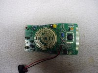
Extech MN35 Digital Mini Multimeter
Extech MN35 Digital Mini Multimeter
That's my guess, just curious what part gave up? it was a nice meter with a large, easy to read display... anything except a propitiatory chip could be replaced...
Its weak point is the 600VDCV range...
Its weak point is the 600VDCV range...
Possibly it has been cooked? Fuse blown is the sign. Replacement is the fastest answer and then have a look at repairing the damaged MN35. Probably not worth bothering with.
Extech MN35 Digital Mini Multimeter
Just looked at it again, thru magnification,,, seems there are 3 of those little square resistors open on a V+ trace,,, don't know the values tho.. I checked the two transistors, they seem OK...
I'm sure a 20 buck DMM isn't worth much trouble,, But, the learnin is priceless!!!
If I could find the values of R15-17,, I'd add em to teh next Mouser order, just to see if I could replace them... doubt there's any schematics around for these!!!
But, the learnin is priceless!!!
I agree and that is why I personally fix things that are beyond economic repair myself. Helping others is another way for me to learn.
If I could find the values of R15-17,, doubt there's any schematics around for these!!!
Post some clear focused pictures of the entire pcb and then a close of the R15-17 area. We can probably deduce what the resistor values are since most of the manual range meters have similar network resistor divider values.
BTW, the mA uses the same the volts/ohms input jack. Many Extech meters (simply rebranded CEM Instruments) have spongy rotary switches meaning it could over rotate. If you were measuring ACV and accidently switched to to 200mA or it over rotated on its own and didn't notice it, then the fuse would blow.
anything except a propitiatory chip could be replaced...
For the MN 35 price point of $20 USD, it is highly unlikely to be using some sort of custom chip.
That chip is likely to be some variation of the Intersil 7106. A chip that Intersil and Fluke both developed.
Thanks!!
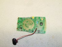
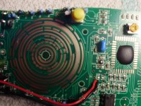
Here ya go,,, The 3 resistors are along the top edge of the pic, arranged vertically about 1/2" to the right of the yellow hold button, and 1/2' above the blue cap...R15 is next to the edge,,, these resistors look burned, the numbers are no longer legible...
I'm assuming they are open, the meter I checked them with has a 2M max ohm scale...
Attachments
The pictures are too blurry and not enough resolution (zoomed out too far).
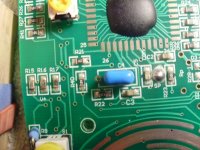
Take the PCB outside or next to a sunny window ledge. Put your camera on macro mode and take more pictures. Please also take a close up of R15, R16 and R17. Maybe try to clean the surface of these 3 resistors with some isopropyl alcohol to make it more readable.
Take the PCB outside or next to a sunny window ledge. Put your camera on macro mode and take more pictures. Please also take a close up of R15, R16 and R17. Maybe try to clean the surface of these 3 resistors with some isopropyl alcohol to make it more readable.
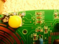
Try these,,, best I could do under a floodlight, getting dark here...
Thanks for helping...
Stick a fork in them - they are done! All of the magic smoke left long ago.
Sorry.
Stick a fork in them - they are done! All of the magic smoke left long ago.
Sorry.
No problem, resistors are still available...
For those who think it isn't worth fixing, stop right here and move onto the next thread.
The person on eevblog that had an Extech MN35 sold it after getting some new meters. So we can't get any pictures or comparison readings.
New DMM vs high-end older ones - Page 1
Nonetheless, we can still try to guess at the values and make some tests.
If you are willing to experiment and learn, then let's try the following. There might be a lot of dead ends or wrong turns, but that is part of the learning process.
So we know R15, R16 and R17 are likely open circuit. Since we don't have a schematic or another similar meter to compare to, I suggest we guess at the values just to see if the main IC stops displaying/flashing -1.
For all 3 resistors, I suggest you try 10k ohm resistor. Any through hole carbon film resistor will do for test purposes.
After you replace them, we can proceed from there with more tests and measurements.
BTW, the cheaper meters lack input protection and it is quite possible the main IC is fried (flashing -1). It isn't easy to test the main IC, but we can eliminate a lot of the obvious easy things first.
OK,,, thanks for replying,, let me catch you up,,, I have a few of the "free" HF DMMs, sometimes they work, but not for long! Anyway, I opened one up this morning, and studied/compared the circuit,,, seems there are three resistors stamped 470, in about the same place as the Extech... I tested them and and got approx 470k each... so I swapped em to R15-17... Seems the top trace to R15 is missing, may have burned off when it shorted, but I can't tell where it was connected, as there is no pad or trace to solder the top of R15 to the PCB, but there is no burn mark, or ghost, to follow either... I tried it anyway, and got teh display to fluctuate different digits, but it isn't working, still open I guess... We can't swap in any resistors bigger than the little square ones "just to test it" (my 1st thought also), because they are on the same side of the board as teh selector knob, and there won't be enough room to assemble/try it...
Now, don't get me wrong, I ain't giving up, as I've been an electrical (not electronic!!) trouble shooter for 45 years, and usually find a way...
If I could see the insides of a working MN35, I think we could nail it...
Thanks again for the support...
Now, don't get me wrong, I ain't giving up, as I've been an electrical (not electronic!!) trouble shooter for 45 years, and usually find a way...
If I could see the insides of a working MN35, I think we could nail it...
Thanks again for the support...
Last edited:
Regarding the R15 connection, aren't all three in series, with vias in between? Looks to me like the top of R15 is connected to the top of R16.
Thanks for replying,,,
I can see the trace between R16 and R17... and the pic looks like there may be a trace between R15 and 16, thru the hole, now that you pointed it out... However, there isn't a pad under the top of R15, but I can easily jump it to the top of R16 with wire... Would they have used three 470k in series?
The only concern I have is the value of the resistors,,, didn't want to try too many different ones, as I don't think the PCB will survive much more soldering!
Last edited:
Since the top of R15 was obviously soldered in the photo, maybe you lifted the pad in the de-soldering process?
It is fairly common in DMMs to find several resistors used in series instead of a single resistor. It's an effective way of increasing the voltage rating and power dissipation capability. These got smoked, so they could be part of the voltage divider, or low-range current shunts, who knows. I can't really tell without having the thing in front of me to laboriously trace out where the connections go, sorry.
The pictures I find of the MN35 suggest that its underlying design will be very very similar to 830-style meters like the Hazard Fraught DMM. But it looks like a bit more effort went into this PCB (I even see some isolation cut-outs), so I would not expect the layout to be similar. The fact that the 470K resistors were in a corresponding location doesn't mean all that much. I suppose that for experiment's sake, 470K is about as good as the 10K earlier suggested, just to see if functionality changes/improves with something in there. Yep, pictures inside a working unit or schematics sure would help!
Update,,,
I do appreciate the positive input! There's well more than 20bux worth of experience here,, and after all, thats why I asked!!!
I just tried putting the three 470k in series, and I get a 1 on the ohms scale,,, Reading a 250R WW, I get 895ohm.. so we got its attention... DCV volt range is not stable it reads 18.8.5 on any range...
My guess is the 470k are the wrong value,,, for starters...
Thanks again for playing along!
I just tried putting the three 470k in series, and I get a 1 on the ohms scale,,,
So with the probes shorted, what do you see on the 200 ohms setting?
Reading a 250R WW, I get 895ohm.. so we got its attention...
What does it show when you measure a 1k ohm resistor?
DCV volt range is not stable it reads 18.8.5 on any range...
With the probes shorted, what do you see on the 2VDC setting?
BTW, if the display shows 1.8.8.8 that could be a sign that the main IC is fried. The "5" you see could easily be an "8" if a couple of the 7 segment display is fried or acting funny.
According to the 7106 datasheet
http://www.intersil.com/content/dam/Intersil/documents/icl7/icl7106-07-07s.pdf
When TEST is pulled high (to V+) all segments will be turned on and the display should read “1888”.
PS. With regards to tracing out what R15, R16 and R17 do, take the pcb and shine a very bright light behind it. Alternatively, put the pcb facing the sun and take a picture of it like how I did. The transparency photo might help you trace out the layout.
UEI DM393 - repair advice all segments on all the time - Page 1
- Status
- Not open for further replies.
- Home
- Design & Build
- Equipment & Tools
- Extech MN35 DMM problem...