Hello,
Last year I bought a used Exposure 2010 and used for about 6 months. First problem was, right audio channel started to give very distorted sound suddenly. I decided to take it away and try to repair it some time later.
After sometime I decided to take the casing out and take a look at the very big output capacitors. I couldn't see anything wrong so plugged it in to check channel outputs again/ This time even power led didn't turn on and amplifier didn't respond to the remote controller. However I heard the click sound that I always heard at the startup. I checked voltage levels and output capacitors had some voltage when turned on. I guess it was 60V or something. What could be wrong with the amplifier? How can I troubleshoot? Should I change all small capacitors on the board?
No, 60v on one rail capacitor is a good sign. Using a clip lead on the speaker ground, and one hand at a time, check the other one too. One will have 60 on plus and the other one will have -60 on minus. Or 35 - 70, they should be about equal.Last year I bought a used Exposure 2010 and used for about 6 months. First problem was, rigI checked voltage levels and output capacitors had some voltage when turned on. I guess it was 60V or something. What could be wrong with the amplifier? How can I troubleshoot? Should I change all small capacitors on the board?
One hand at a time because >24 v across your heart can stop it. Keep one hand in pocket if you're impulsive.
Other safety necessity, wear no jewelry on hands wrists or neck. 1 v @ 30 amp through a ring can burn your flesh to charcoal. Also wear safety glasses, failures in power amps can cause parts to explode. Also unsoldering solder can splash & ruin your eye.
When changing parts, newbies make about 50% bad solder joints. change 1 thing at a time then listen to see if you made it better or worse. Worse, you know right where you put a bad solder joint or the wrong part or something.
DC coming out of the output transistors is a bad sign. <.2v allowed at the input of the protection relay. That is what usually makes the clicking sound. Probe on the ends of the 2 coils near the relay, that is where the output transistor signal runs through. Coils are about 1 cm diameter by 3 cm long. Installed for RF block into the feedback path.
If no DC on output, you may have a connection problem. With power off reseat any board connectors, spray out the volume pot with contact cleaner, also any source switches like CD/FM/LP.
You can trace the music with an analog VOM, cheaper than a scope and lasts longer. This one Volt Ohm Amp AC DC Battery Tester Meter Gauge Analog Multimeter 987792599984 | eBay
has a 10 vac scale, should be suitable for tracing inputs. You use the 50 vac scale or 100 vac scale after the VAS and for drivers & output transistors. those transistors are bigger & have heat sink tabs. the input transistors are tiny with no heat sink. Put a .047 >200 v film cap series the ground connection of the meter, which you connect to the speaker return with a couple of clip leads. They have clip leads at harbor freight but their meters lie a lot, not worth $1. DVM also produce random numbers on music, the AC scale is for 50-60 hz wall voltage.
if the music comes in, doesn't go out the output relay, there is a problem in the middle. Finding where it stops points out where the problem is. I use a $5 FM radio earphone jack as a signal source, turn the volume down to 1/3, more than that the signal is too loud. If you use your cell phone, and DC comes out the input jack, you just ruined a >$250 cell phone. Make sure radio is putting out music with an earphone before substituting the RCA plug adapter.
Connection problem is often punchdown blocks or the output relay. Punchdown blocks can be pushed tighter. Relays have to be replaced.
If you have to order the blocking capacitor, also order a couple of meter fuses of the right size. Boxes from newark/digikey/mouser start at $8 even if one thing is in them . Two things is still $8. 1/8" stereo earphone plug to dual RCA plugs or dual 1/4 phone plugs adapter for radio can go in same box.
Happy hunting.
Last edited:
Thanks a lot for your detailed answer. I just remembered that when I checked to board I found out that one of the fuses was blown. So I changed it but didn't work out, just fyi. I am actually electronics engineer so I'm not new to soldering. Analog vom is neat trick I'll get one asap. Maybe I can also get a cheap chinese oscilloscope. Unfortunately I don't have digikey here but I'll be able to get things locally.
First problem was, right audio channel started to give very distorted sound suddenly. I decided to take it away and try to repair it some time later.
After sometime I decided to take the casing out and take a look at the very big output capacitors. I couldn't see anything wrong so plugged it in to check channel outputs again/ This time even power led didn't turn on and amplifier didn't respond to the remote controller.
Your amp has no speaker protection circuit, please don't connect any speaker to it when you testing your amp.
To check your amp, first double check all fuses and then measure all the supply voltages output form the the transformer, no power led light, no remote control function and no sound maybe no supply voltage for remote control and pre-amp circuit.
Please check the power amp supply voltage(big power supply cap), there should be an almost equal +V and -V supply voltage, also the regulation voltage for the opamp(driver IC pin4 and pin8), if these voltages are correct then your power amp section seems ok, in case your MCU for remote control function fail, you can input signal direct to the vol pot and connect a "testing speaker" to the amp output for a listening test.
It is almost like these procedures to check and repair an amp, check fuse, check physical damage components, check PCB dry solder joints, check all the power supply voltages, then check each function block form input selection circuit, pre-amp, vol pot to power amp section and each function block can be tested separately.
Good luck to you!
Attachments

Last edited:
I just went to check voltage levels on board. Before plugging in I checked fuses and reinserted them. Plugged in and leds are working. Before I only checked 3.15a power fuses and changed them, now I also checked 315ma fuse, didn't change it tho'. My guess is there was a contact problem on 315ma fuse.
Now how should I test it before connecting speakers?
Now how should I test it before connecting speakers?
I forgot to mention in previous post, remote started to work as well. I tried to check speaker output connectors voltage, in AC mode of voltmeter, left channel showed 7.6V Ac and right channel showed 6.8V Ac, no input connected btw. These values didn't change with me increasing volume knob. I decided to check if it works with my old speaker and everything seems working fine now.
While everything opened up I checked some voltage levels for future reference. I'll use patrick101s drawing and opamp pinout to refer pins I'm measuring. I am writing on the phone sorry for any mistake, and I'll try to write it down as table. On table Ref means where I put my black cable of voltmeter, target means red cable.
Do you see anything wrong here?
Ref. , target. , output
Cap gnd , Cap V+ , 36.4V
Cap gnd , Cap V- , -36.4V
Opamp V- , Opamp V+ , 29.2V
Opamp V- , Opamp outA , -14.67V
Opamp V- , Opamp outB , -13.79V
Cap gnd , opamp V+ , 14V
Cap gnd , opamp V- , -14V
Edit: well i tried to make spaced formatting for table but it doesn't work i guess...
Last edited:
You can check output safely with a speaker by putting a non-polar capacitor in series. Say a 1000 uf 50 vnp, or two 2200 50 v capacitors series minus to minus. This would protect your speaker from DC out, at the cost of sounding a little funny. Bass will be missing. Low wattage (1 vac) with series polar capacitors just sounds funny, perhaps due to chemical events. DC voltage on speaker is very bad for them, make sure the amp is not doing that before taking the cap out. 200 mv max on speaker.
The "opamp V-" of 29.2 v sounds extremely wrong. Why are there two readings next to the name? One channel A one channel B?
Also "opamp out" of -14 to -13 sound extremely wrong. Your meter ground was on the speaker ground wasn't it. Or on the common terminal of the two rail caps? (the big ones). opamp out pins 7 & 1 should read on DC scale about zero, the same as the + and - inputs. If the power pins DC voltages are centered around the speaker ground.
There are a dozen caps around the op amps, "cap gnd" doesn't mean a lot to me. There should be one + one and one - one but which are connected to the power pins of the op amp is undetermined.
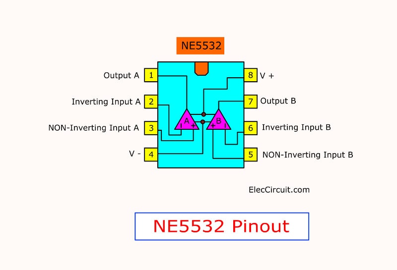
We all have the pinout of the ne5532, no need to reproduce it. Datasheet available on datasheetcatalog.com
I've found cheap DVM make random numbers on AC scale on frequencies other than 50 hz or 60 hz. To read music AC readings you need a $180 Fluke RMS dvm, or a scope, or a $20 analog VOM with 50 vac and 10 vac scales. You use the analog VOM with a .047 uf >100 v cap between negative lead and the speaker ground, to prevent it reading AC on DC voltages. Scopes are full of electrolytic capacitors that can fail in 10-20 years. Don't buy a used one. I do without. The fluke RMS DVM reads anything above 7000 hz as zero. Big lie if your circuit is oscillating ultrasonically. I won't buy one. The $20 analog VOM will see ultrasonic oscillations fine, just oscillation won't have the beats of the drum of music on the pointer. I use $5 radio for input source, not a signal generator.
BTW I've found electrolytic caps from the front shelves of the TV parts store lasted 5-10 years. Caps from distributors with a service life above 3000 hours, I haven't worn any out yet since I started reworking everything in 2008. About 300 caps in organs & amps. farnell,digikey,mouser, arrow, RS of UK, Reichelt of Ger, are real distributors. Farnell & digikey will tell you cap service life in the selector table.
If you found the speaker fuses blown, it is worth checking power off the output transistors with diode scale or 2000 ohms scale. B-E B-C either .450-.700 v (ohms) plus or minus depending on polarity. These are the transistors on the heat sink, and base is the one on the left with the writing facing you & up. Blown OT's is a very common fault. Zero is very bad news. Emitter resistors often blow with them.
The "opamp V-" of 29.2 v sounds extremely wrong. Why are there two readings next to the name? One channel A one channel B?
Also "opamp out" of -14 to -13 sound extremely wrong. Your meter ground was on the speaker ground wasn't it. Or on the common terminal of the two rail caps? (the big ones). opamp out pins 7 & 1 should read on DC scale about zero, the same as the + and - inputs. If the power pins DC voltages are centered around the speaker ground.
There are a dozen caps around the op amps, "cap gnd" doesn't mean a lot to me. There should be one + one and one - one but which are connected to the power pins of the op amp is undetermined.
We all have the pinout of the ne5532, no need to reproduce it. Datasheet available on datasheetcatalog.com
I've found cheap DVM make random numbers on AC scale on frequencies other than 50 hz or 60 hz. To read music AC readings you need a $180 Fluke RMS dvm, or a scope, or a $20 analog VOM with 50 vac and 10 vac scales. You use the analog VOM with a .047 uf >100 v cap between negative lead and the speaker ground, to prevent it reading AC on DC voltages. Scopes are full of electrolytic capacitors that can fail in 10-20 years. Don't buy a used one. I do without. The fluke RMS DVM reads anything above 7000 hz as zero. Big lie if your circuit is oscillating ultrasonically. I won't buy one. The $20 analog VOM will see ultrasonic oscillations fine, just oscillation won't have the beats of the drum of music on the pointer. I use $5 radio for input source, not a signal generator.
BTW I've found electrolytic caps from the front shelves of the TV parts store lasted 5-10 years. Caps from distributors with a service life above 3000 hours, I haven't worn any out yet since I started reworking everything in 2008. About 300 caps in organs & amps. farnell,digikey,mouser, arrow, RS of UK, Reichelt of Ger, are real distributors. Farnell & digikey will tell you cap service life in the selector table.
If you found the speaker fuses blown, it is worth checking power off the output transistors with diode scale or 2000 ohms scale. B-E B-C either .450-.700 v (ohms) plus or minus depending on polarity. These are the transistors on the heat sink, and base is the one on the left with the writing facing you & up. Blown OT's is a very common fault. Zero is very bad news. Emitter resistors often blow with them.
Last edited:
Right now amplifier seems to work fine with my Monitor Audio Rx1. I had 1.6a fuse instead of 3.15a fuse so I used them but I will change them asap with 3.15a. In the end I only changed fuses so I assume nothing wrong with the board. If a fuse would blown soon I would check transistors as well. Thank you indianajo and patrick101 for your help.

@indianajo I guess I didn't explain it clear. When I write [Opamp V- , Opamp V+ , 29.2V] it means I measure the voltage between V- pin and V+ pin. There is two big Capacitors I assumed negative side of these would be connected to ground. As far as I understand board ground is 0V, opamp Vcc- is -14V, opamp Vcc+ is +14V.
I didn't do much testing. I don't know wether both channel outputs equally and stable.
I'm trying to get capacitors from reputable sources as well. However we don't have farnell or mauser here unfortunately. Most seller do sell cheap chinese caps. It's hard to find panasonic caps for me. Ordering from abroad is not favorable because of the shipping fees and customs process.
Right now amplifier seems to work fine with my Monitor Audio Rx1. I had 1.6a fuse instead of 3.15a fuse so I used them but I will change them asap with 3.15a. In the end I only changed fuses so I assume nothing wrong with the board. If a fuse would blown soon I would check transistors as well.
I didn't do much testing. I don't know wether both channel outputs equally and stable.
I'm trying to get capacitors from reputable sources as well. However we don't have farnell or mauser here unfortunately. Most seller do sell cheap chinese caps. It's hard to find panasonic caps for me. Ordering from abroad is not favorable because of the shipping fees and customs process.
I'm happy that your amp is working again.
You can just check the amp output DC voltages, if the voltages are small and the amp case(part of heatsink) temperature is not so high when idling, then your amp should all ok.
Last edited:
If your output is below 200 mv dc, probably nothing else is wrong. 3 a fuses will be inaudibly different than 3.15 amp fuses which you won't find. The ear is logrithmic, look at the decibel scale.I'm trying to get capacitors from reputable sources as well. However we don't have farnell or mauser here unfortunately. Most seller do sell cheap chinese caps. It's hard to find panasonic caps for me. Ordering from abroad is not favorable because of the shipping fees and customs process.
When the amp gets 15-20 years old and the power goes away, top quality brand caps besides panasonic are nichicon, rubicon, Vishay, 2nd tier united chemicon & cde. I found store caps were all short life garbage, even in Houston, TX. Leave caps alone if you can't get 3000 to 10000 hour caps from an distributor. The store in Louisville KY was selling rejects, I suppose he got a bargain on them. All brands sell 5 year 1000 hour caps for the repairmen that want you back with a wimpy amp in 2-4 years. You have to select the 7-20 years (3000 to 10000 hour) caps from national stock of a real distributor. Once they are out of the bag with the distributor logo & PartNumber on them, you can't tell the junk apart from the real deal.
You may have been right about the 315 ma fuse losing connection, clips can do that. Might do it again.
If your output is below 200 mv dc, probably nothing else is wrong. 3 a fuses will be inaudibly different than 3.15 amp fuses which you won't find. The ear is logrithmic, look at the decibel scale.
When the amp gets 15-20 years old and the power goes away, top quality brand caps besides panasonic are nichicon, rubicon, Vishay, 2nd tier united chemicon & cde. I found store caps were all short life garbage, even in Houston, TX. Leave caps alone if you can't get 3000 to 10000 hour caps from an distributor. The store in Louisville KY was selling rejects, I suppose he got a bargain on them. All brands sell 5 year 1000 hour caps for the repairmen that want you back with a wimpy amp in 2-4 years. You have to select the 7-20 years (3000 to 10000 hour) caps from national stock of a real distributor. Once they are out of the bag with the distributor logo & PartNumber on them, you can't tell the junk apart from the real deal.
You may have been right about the 315 ma fuse losing connection, clips can do that. Might do it again.
I'm not gonna fiddle with exposure 2010 more. However I have a Dacmagic+ and Roland XP50 to restore and I need caps for them. I bought low quality ones but no other option right now.
- Home
- Amplifiers
- Solid State
- Exposure 2010 doesnt give any output