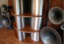
Hi guys i posted this horn i made a while back and have just tested to to fine almost no again at all 
I used this equaion to work out the throat of the horn
Area throat = (2pie*Fs*Qts*Vas)/c
was this wrong should i have just had made the troat area the same size as the speaker cone area ?
These where the speaker parameters
Can any one tell me why this went so wrong ?
An externally hosted image should be here but it was not working when we last tested it.
I used this equaion to work out the throat of the horn
Area throat = (2pie*Fs*Qts*Vas)/c
was this wrong should i have just had made the troat area the same size as the speaker cone area ?
These where the speaker parameters
An externally hosted image should be here but it was not working when we last tested it.
Can any one tell me why this went so wrong ?
You haven't got it connected to your amp! I learned a long time ago to check the obvious stuff first. 😀
Of coures i had it connected when i tested it, this was just a good picture to show off the design. Its not the finised article. When i said i had no gains i ment i had no increase in SPL responce compared to the speakers in free air.
How about that isobarik wiring? Are you positive the drivers are wired out of phase? Also, are you sure you don't have any air leakage between your front and rear chambers. The setup looks tough to put the cap on and make sure everything is properly sealed. Also, how did you account for the isobarik loading with regard to the throat size?
The "gain" in SPL from a horn, or any other passive acoustical transformer or device occurs only because it can concentrate isotropically radiated power, the power illuminating a sphere, to a smaller area. If all of the sound hitting a sphere is concentrated to hit just half a sphere then the sound pressure will double, or you will have seen 3 dB gain. The effect of a horn will not be seen in the vicinity of the mouth as being louder than at the transducer. It is in the farfield where the horn is aimed where an increase in level can be measured by comparison to the same distance from the free air driver. Some clever wag comes along periodically and figures out a way to extrapolate near field measurements to predict the expected performance in the far field.
I doubled checked my wiring but, if i had wired them in phase then surly my responce would be almost nothing. I took the parameters for the isobaric config to deisgn the horn, ie plugged the second set of numbers in the table into the throat eq (etc). I must admit due to the small size of the coil i cant confirm that the top base fitted on correclty. I might try and get it x-rayed to see if it was properly alined.
Still tho was i right to use that throat equation ?
Also for testing how do i make sure i only supply 1 watt to the speaker ?
Still tho was i right to use that throat equation ?
Also for testing how do i make sure i only supply 1 watt to the speaker ?
rcavictim you seem to have good knlodge on this subject, i used Hornresp to orginally model the system but i wonder if you could tell me what equations are used to model horn SPL, as i would like to do the calculations my self.
Thanks for all your quick replies keep them coming
Thanks for all your quick replies keep them coming
I think the problem may be in an inadequate throat size. You're talking only about 10% of Sd. I thought it looked too small in your original post. Some of the old horn theory work suggests a throat/Sd ratio of 30-100%.
Re wiring: In phase wouldn't be no sound like if a W baffle dipole was wired wrong and result in total cancellation. There would be sound, just bad sound due to the tiny rear chamber (airspace between the 2 drivers).
I have a feeling though that the problem is leakage. The way I would have done the top cap would be to route out a grove for the horn and baffle. Fill the groove with a non-silicone caulk. Then fit the horn and baffle assembly into the groove. Not having the baffle flush with the metal edge in your pic is what concerns me about a proper seal right at the baffle.
I wouldn't give up quite yet, even if the seal appears good. I'd take the cap off and bend the top edge of the metal forming the throat up to where the horn and the baffle first meet, just enough so it looks like that first segment (up to the baffle) looks like there is no flare rate. The bottom will still be flared and you'll just have a first net first segment at a lower expansion rate frequency. That is commonly used to decrease the size of a horn and will have less of a negative impact than your very high height to width ratio of your horn pathway. That would be an easy way to get more throat size with minimal effort. To test it, before reassembly, lay a thin sheet of foam rubber covering all of the edges to form a seal. Put a piece of plywood on. Add a bunch of weight or have someone sit on it and give it a listen.
Good Luck!!!
VERY clever though. Routing the slots would be too much work IMHO, considering how easy this is to make.
I have to agree- the horn doesn't get big enough at the opening. I think your taper is wrong...
I have to agree- the horn doesn't get big enough at the opening. I think your taper is wrong...
Piper said:rcavictim you seem to have good knlodge on this subject, i used Hornresp to orginally model the system but i wonder if you could tell me what equations are used to model horn SPL, as i would like to do the calculations my self.
Thanks for all your quick replies keep them coming
Piper,
Unfortunately I am not the fellow to assist you when it comes to mathematical analysis. I've learned to get by very well by faking it. My hands do most of the thinking and for me at least it seems to work as I cannot fault the very high quality and success rate of my projects. This is not a formula for success that one can write down and post.
My feelings are also that the throat area is too small and also that the mouth should be way larger. Your mouth should be a wavelength in circumference to the wavelength reproduced on a true horn.
Take a look at this image. I think you are on to a clever design but suspect that it is the same that goes on inside this commercial offering from AvanteGarde. In this case they take what you have (apparently) and at the mouth they form an opposite roll to produce a good diffraction free mouth opening which is what I was about to suggest to you as well for your design.
Attachments
Can you post the hornresp parameters and T/S-parameters so it's easier to see what should be changed? Also makes it easier to tell what you should look for when designing a horn.
Mvg Johan
Mvg Johan
This was what i enter into hornrep and the T/S paramaters
If my throat was too small does that mean that orginal equation i used
Area throat = (2pie*Fs*Qts*Vas)/c
- was wrong or would it mean that the speakers i unstable were not suited for for horn use (there were cheap)
An externally hosted image should be here but it was not working when we last tested it.
An externally hosted image should be here but it was not working when we last tested it.
If my throat was too small does that mean that orginal equation i used
Area throat = (2pie*Fs*Qts*Vas)/c
- was wrong or would it mean that the speakers i unstable were not suited for for horn use (there were cheap)
And these were my results
Thanks again for taking time to help me
An externally hosted image should be here but it was not working when we last tested it.
Thanks again for taking time to help me
My gut feeling is that the cavity between the driver and the horn mouth is too large. This cavity acts as a lowpass filter. Does the software you use take this cavity into account? If not, you could try to fill the cavity with cleverly cut pieces of wood, to minimize its volume.
But as I said, it is just a gut feeling.
But as I said, it is just a gut feeling.
Hi Piper
I tried to model your horn in Hornrespons using
your parameters, and I got this:
Is this similar to your results?
cheers , Jan
EDIT:
OK , the image didn't seem to load.
Anyway , I got modelled response down to about 100Hz,
but very ragged. I'll try again.
I tried to model your horn in Hornrespons using
your parameters, and I got this:
Is this similar to your results?
cheers , Jan
EDIT:
OK , the image didn't seem to load.
Anyway , I got modelled response down to about 100Hz,
but very ragged. I'll try again.
Some direct points:
If Iam not mistaken VTC is in cm3 (not liters) so it should be 2700 instead of 2.7. The volume of the VTC can change the low-frequency response a lot.
ATC is the same as Sd (in this case anyway I think), where S1 is the only factor in this case determing the compressionfactor.
And as already told:
The compressionfactor is pretty high. Personally I would try to make things work with a factor close to 4 at most.
The moutharea is really small. A moutharea around minimal 4 times bigger than Sd works best for my own designs, where I want low end extension.
Doesn't Cms and Mmd change? Mmd would change a little bit anyway because of the air between the driver ads weight to the Mmd. But don't know if it would matter that much (difference between practice and simulation anyway).
According to the T/S-parameters the speakers seem to be good enough for hornloading.
Why use isobaric? It makes the rear chamber a bit smaller but you could really benefit from double Vd here.
I will simulate at home but since my internet is down there I probably won't respond before Tuesday.
Have a nice Easter!😉
Mvg Johan
Hi Piper
Had another go in Hornresponse,
got response down to about 70Hz at 97dB,if stuck in a corner.
This with a horn with a 4700 sq.cm mouth and a length of 300cm,
which is probably a bit bigger than what you had in mind?
This was with a single driver.
cheers, Jan
Had another go in Hornresponse,
got response down to about 70Hz at 97dB,if stuck in a corner.
This with a horn with a 4700 sq.cm mouth and a length of 300cm,
which is probably a bit bigger than what you had in mind?
This was with a single driver.
cheers, Jan
Yes the compression ratio works out to be 1:8, which is very small indead, this was because i based it on that dam throat area equation not really knowing much about comprssion ratios at the time.
I didnt know wht Cms and Mmd where ment to represnt so i left them at defeaults
Your right as well ATC, was entered wrong my responce now matchs up like so >
Tomorrow i will remove the casing and see if every thing was sealed down, then try and reduce the throat chamber.Then ill reseal using a rubber backing on one side. Lets hope this will give me some in improvments.
I didnt know wht Cms and Mmd where ment to represnt so i left them at defeaults
Your right as well ATC, was entered wrong my responce now matchs up like so >
An externally hosted image should be here but it was not working when we last tested it.
Tomorrow i will remove the casing and see if every thing was sealed down, then try and reduce the throat chamber.Then ill reseal using a rubber backing on one side. Lets hope this will give me some in improvments.
Piper said:Yes the compression ratio works out to be 1:8, which is very small indead, this was because i based it on that dam throat area equation not really knowing much about comprssion ratios at the time.
I didnt know wht Cms and Mmd where ment to represnt so i left them at defeaults
Your right as well ATC, was entered wrong my responce now matchs up like so >
.
Put mouse over boxes to get info down the bottom.
Double click odd units to get input boxes eg Cms uses Vas input
I did do that, just I didn't know what it was really asking for and how to work out
1: CMS - driver diaphragm suspension mechanical compliance (m/N)
2: MMD - driver diaphragm and voice coil dynamic mechanical mass (m/N)
I asume MMD is refering to the magnet mass and cone mass but how the hell do you get it into units of m/Newton i.e. distance/force

1: CMS - driver diaphragm suspension mechanical compliance (m/N)
2: MMD - driver diaphragm and voice coil dynamic mechanical mass (m/N)
I asume MMD is refering to the magnet mass and cone mass but how the hell do you get it into units of m/Newton i.e. distance/force
- Status
- Not open for further replies.
- Home
- Loudspeakers
- Subwoofers
- Exponetial horn gone very wrong