Here's a circuit I came up with to honor the original Garnet Herzog distortion unit. Comments are welcome. Also, tube-amp experts are invited to offer criticisms and/or point out mistakes I may have made in the design. I have not built it, so it must be considered experimental circuitry. Yet, I believe it will work. Thanks.
Tube-Type Overdrive Preamp
By H.K. Richter
Here is my design for a preamp intended for producing distortion inspired by the original Garnet Herzog amp, though this is wholly my own design. The Herzog was built for the guitarist Randy Bachman, famous in the ‘60s while playing with the band The Guess Who, using the Herzog on hit song “American Woman”. And in the ‘70s he had the hit “Takin’ Care of Business” with his own band, Bachman Turner Overdrive, again using the Herzog, which had been made for him by Canadian engineer Gar Gillies, founder of the Garnet amp company. In the ‘60s, distorted guitar sounds were achieved by using amps turned up to maximum volume, since there were few stomp-box types of effects at the time. Bachman’s distorted sound therefore stood out, and thus, after the “American Woman” hit, the Herzog was suddenly in demand by other guitarists, and Garnet amps, already popular, also saw sales increase greatly for all of their products.

The design used by Gar Gillies for the Herzog was likely from his low-power practice-amp called the Banshee, with which he simply replaced the speaker with an output jack sending out a high-impedance line-level signal instead of a speaker signal. Hence, the Herzog was one of the first of all purpose-built distortion effect boxes that sounded good. Yet, the Banshee had earlier been based on the Fender Champ. So, the first version of the Herzog, made at Randy Bachman’s request (and with his help), was just a complete low-power single-end amp having a line out instead of a speaker. Later versions, however, included both a line out jack and a speaker jack. In any case, after studying singe-ended amps, and having previously become acquainted with the Herzog schematic, I decided to come up with something similar, though my design is not based on an existing amp, but uses circuits obtained from the original 1965 RCA Receiving Tube manual, along with the design tables and tube characteristics graphs in that manual. I also studied design tables and schematics online and investigated many forums about tube-amps.
Example Source: https://www.thetubestore.com/guitar-amp-schematics
My design is therefore unique to me, though similarities between my circuit and many other single-ended amp circuits are evident, because there are scant few topologies available that actually work properly, and which were long ago published by vacuum tube manufacturers, such as RCA, in their tube manuals. It’s from those manuals that Leo Fender and all other early guitar-amp makers obtained their first circuits, so then I decided to do the same thing, instead of copying their designs like so many other guitar-amp makers had done early on (e.g., Garnet, Marshall, etc.).
Here is the power supply for my Overdrive Preamp. I call this overall design a preamp because that’s actually what it is, despite having what is normally used as an output stage. Just as with the Herzog, the output tube is used to make the final circuit a gain stage, so that it serves as a preamp tube, though it was designed as an output tube. The reason is to obtain the sound of its distortion when overdriven.

Notice the Input Tone control in the input triode’s circuit. I obtained that idea from an old book from the ‘50s called “High Fidelity Techniques”, by MIT professor John H. Newitt. Copyrighted in 1955, the book must have become popular with audiophiles back then, since it had been reprinted seven times as of four years later (I have a 7th printing). How many more reprints it had after that I don’t know. The point is that it contains a wealth of information and many tube circuits the author actually built and tested, including the said tone-control. This one, however, mostly affects the mids, leaving extreme highs and lows alone.
The Gain control is of my own device and is used to adjust the current through the input triode. When all the way up, the gain for the input triode is 13, despite the rated maximum for such circuit at 17 and an absolute maximum gain for the triode at only 19. Yet, the next triode provides a fixed gain of 16. However, any of the pin-compatible tubes listed in the diagram will provide more gain from both stages. Here’s a chart.
Tube 1st Triode 2nd Triode Maximum
Type Gain In Circuit Gain In Circuit Gain Rating
12AU7A 13 16 19
12AY7 23 35 44
12AT7 24 37 60
12AX7A 32 62 100
For the least gain, and therefore the least amount of distortion, keep the 12AU7A, but for more gain and distortion, experiment by substituting something other than the said 12AU7A, for which this design was originally tailored. But just because you’ll get more gain, that does not mean you’ll get better tone. Tonality is subjective. Some guitarists like more fuzz than others, so a builder of this design must decide which tube sounds best to them. Have one of each on hand during final testing so you can contrast and compare. Know beforehand, however, that more gain, giving increased distortion, logically corresponds to more output volume. That’s why there’s such a large-valued pot as the Master Volume control. 1M should be enough to work for a volume pot in this case, but if you find the output too strong with a higher-gain tube, increase the value of the resistor at the 8-ohm tap of the output transformer.
Next in the signal path is the Dist 1 control, which sets the amount of signal going to the second triode, and thus how greatly that triode is overdriven. Then comes the Dist Tone control, which is a low-pass filter with a high cutoff and only affects the highs but if it’s turned down the volume goes down too. So, it must be adjusted to taste by trial-and-error, then left at a preferred position. Following that control is the Dist 2 control which affects the signal level going to the output tube. The reason it’s labeled as a distortion control instead of as a volume control is that it is meant to adjust how much the output tube is overdriven. The primary goal is to get the output tube clipping between 10% and 20%, for the best distortion tone. Preamp tubes will clip, of course, but their distortion involves odd-order harmonics along with even-order harmonics, which is not as sweet as even-order harmonics alone. Also, some preamp tubes, like the 12AX7A, can have an unwanted raspiness in their distortion, and some just sound better than others. But output tubes of any type were originally designed to emphasize even-order harmonics in their distortion. That’s what makes tube-amps sound good when cranked up loud. It’s the even-order harmonics from the output tubes (plus fuzz from the output-transformer).
Much of the output’s sound also comes from the output transformer. The transformer chosen for the output of this project is made to sound as much like one from the ‘50s as possible, using modern materials. And its when the output transformer is saturated that it too introduces even-order harmonics into the fuzz it produces.
The dummy load is there to simulate a speaker, because the output stage needs what it would see as a normal load. But it can be replaced by a real speaker, if desired, or yet another output jack can be installed and labeled properly, such as “Spk”, along with a switch that allows the user to choose to use an external speaker instead, although this amp would only put out about 5 W RMS. In any case, the chosen output tube is not there to drive a speaker, but to get its sound in a line-level output signal.
There is also a choice to be made about which output tube is preferred. The list of pin-compatible substitutes is given in the diagram, together with their maximum possible plate dissipation (wattage) ratings. But there too, the sound of the different types must be compared during final testing, to know which type sounds best to the builder.
EOF
Tube-Type Overdrive Preamp
By H.K. Richter
Here is my design for a preamp intended for producing distortion inspired by the original Garnet Herzog amp, though this is wholly my own design. The Herzog was built for the guitarist Randy Bachman, famous in the ‘60s while playing with the band The Guess Who, using the Herzog on hit song “American Woman”. And in the ‘70s he had the hit “Takin’ Care of Business” with his own band, Bachman Turner Overdrive, again using the Herzog, which had been made for him by Canadian engineer Gar Gillies, founder of the Garnet amp company. In the ‘60s, distorted guitar sounds were achieved by using amps turned up to maximum volume, since there were few stomp-box types of effects at the time. Bachman’s distorted sound therefore stood out, and thus, after the “American Woman” hit, the Herzog was suddenly in demand by other guitarists, and Garnet amps, already popular, also saw sales increase greatly for all of their products.
The design used by Gar Gillies for the Herzog was likely from his low-power practice-amp called the Banshee, with which he simply replaced the speaker with an output jack sending out a high-impedance line-level signal instead of a speaker signal. Hence, the Herzog was one of the first of all purpose-built distortion effect boxes that sounded good. Yet, the Banshee had earlier been based on the Fender Champ. So, the first version of the Herzog, made at Randy Bachman’s request (and with his help), was just a complete low-power single-end amp having a line out instead of a speaker. Later versions, however, included both a line out jack and a speaker jack. In any case, after studying singe-ended amps, and having previously become acquainted with the Herzog schematic, I decided to come up with something similar, though my design is not based on an existing amp, but uses circuits obtained from the original 1965 RCA Receiving Tube manual, along with the design tables and tube characteristics graphs in that manual. I also studied design tables and schematics online and investigated many forums about tube-amps.
Example Source: https://www.thetubestore.com/guitar-amp-schematics
My design is therefore unique to me, though similarities between my circuit and many other single-ended amp circuits are evident, because there are scant few topologies available that actually work properly, and which were long ago published by vacuum tube manufacturers, such as RCA, in their tube manuals. It’s from those manuals that Leo Fender and all other early guitar-amp makers obtained their first circuits, so then I decided to do the same thing, instead of copying their designs like so many other guitar-amp makers had done early on (e.g., Garnet, Marshall, etc.).
Here is the power supply for my Overdrive Preamp. I call this overall design a preamp because that’s actually what it is, despite having what is normally used as an output stage. Just as with the Herzog, the output tube is used to make the final circuit a gain stage, so that it serves as a preamp tube, though it was designed as an output tube. The reason is to obtain the sound of its distortion when overdriven.
Notice the Input Tone control in the input triode’s circuit. I obtained that idea from an old book from the ‘50s called “High Fidelity Techniques”, by MIT professor John H. Newitt. Copyrighted in 1955, the book must have become popular with audiophiles back then, since it had been reprinted seven times as of four years later (I have a 7th printing). How many more reprints it had after that I don’t know. The point is that it contains a wealth of information and many tube circuits the author actually built and tested, including the said tone-control. This one, however, mostly affects the mids, leaving extreme highs and lows alone.
The Gain control is of my own device and is used to adjust the current through the input triode. When all the way up, the gain for the input triode is 13, despite the rated maximum for such circuit at 17 and an absolute maximum gain for the triode at only 19. Yet, the next triode provides a fixed gain of 16. However, any of the pin-compatible tubes listed in the diagram will provide more gain from both stages. Here’s a chart.
Tube 1st Triode 2nd Triode Maximum
Type Gain In Circuit Gain In Circuit Gain Rating
12AU7A 13 16 19
12AY7 23 35 44
12AT7 24 37 60
12AX7A 32 62 100
For the least gain, and therefore the least amount of distortion, keep the 12AU7A, but for more gain and distortion, experiment by substituting something other than the said 12AU7A, for which this design was originally tailored. But just because you’ll get more gain, that does not mean you’ll get better tone. Tonality is subjective. Some guitarists like more fuzz than others, so a builder of this design must decide which tube sounds best to them. Have one of each on hand during final testing so you can contrast and compare. Know beforehand, however, that more gain, giving increased distortion, logically corresponds to more output volume. That’s why there’s such a large-valued pot as the Master Volume control. 1M should be enough to work for a volume pot in this case, but if you find the output too strong with a higher-gain tube, increase the value of the resistor at the 8-ohm tap of the output transformer.
Next in the signal path is the Dist 1 control, which sets the amount of signal going to the second triode, and thus how greatly that triode is overdriven. Then comes the Dist Tone control, which is a low-pass filter with a high cutoff and only affects the highs but if it’s turned down the volume goes down too. So, it must be adjusted to taste by trial-and-error, then left at a preferred position. Following that control is the Dist 2 control which affects the signal level going to the output tube. The reason it’s labeled as a distortion control instead of as a volume control is that it is meant to adjust how much the output tube is overdriven. The primary goal is to get the output tube clipping between 10% and 20%, for the best distortion tone. Preamp tubes will clip, of course, but their distortion involves odd-order harmonics along with even-order harmonics, which is not as sweet as even-order harmonics alone. Also, some preamp tubes, like the 12AX7A, can have an unwanted raspiness in their distortion, and some just sound better than others. But output tubes of any type were originally designed to emphasize even-order harmonics in their distortion. That’s what makes tube-amps sound good when cranked up loud. It’s the even-order harmonics from the output tubes (plus fuzz from the output-transformer).
Much of the output’s sound also comes from the output transformer. The transformer chosen for the output of this project is made to sound as much like one from the ‘50s as possible, using modern materials. And its when the output transformer is saturated that it too introduces even-order harmonics into the fuzz it produces.
The dummy load is there to simulate a speaker, because the output stage needs what it would see as a normal load. But it can be replaced by a real speaker, if desired, or yet another output jack can be installed and labeled properly, such as “Spk”, along with a switch that allows the user to choose to use an external speaker instead, although this amp would only put out about 5 W RMS. In any case, the chosen output tube is not there to drive a speaker, but to get its sound in a line-level output signal.
There is also a choice to be made about which output tube is preferred. The list of pin-compatible substitutes is given in the diagram, together with their maximum possible plate dissipation (wattage) ratings. But there too, the sound of the different types must be compared during final testing, to know which type sounds best to the builder.
EOF
Last edited:
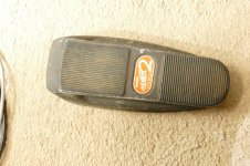
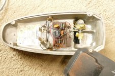
There were stomp box style distortion boxes as far back as the mid 60's. I personally dissected a Vox Tone Bender in 1967 and cloned it. There were at least three different versions of the Tone Bender, two with 3 transistors and one with 2. There was also the Dallas Arbiter Fuzz Face which was a clone of the two transistor version. The two transistor version I cloned was quite sensitive to the germanium transistors used, so I made a little test setup to find a good sounding pair. The gold standard set from a Sony radio are still in it, and I still have it after all these years, and it still works. One may also remember the Gibson Maestro Boomer and Boomer 2 Wah-Wah pedal from the mid 60's. This is a variable frequency bandpass filter controlled by a back and forth pedal. I still have my Boomer 2 from 1967 but it does not work, the pot is frozen, and the gear is stripped. The schematic with Gibson part numbers is inside!In the ‘60s, distorted guitar sounds were achieved by using amps turned up to maximum volume, since there were no stomp-box types of effects at the time.
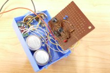
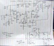
Your circuit should work. It is similar to the Mid 60's Fender Champ which sounds great cranked. I made several "Turbo Champs" in the late 90's that uses a similar circuit but incorporated a TMB tone stack. I made them one at a time somewhat randomly with whatever parts I had over a several year period. No two were exactly the same, and most used car stereo speakers from a closed K-mart store and whatever transformers I could scrounge at the time. This schematic was drawn from memory after the fact, so it may not match any of the amps. I found a picture of a pair of my disco era speakers. The later versions were all black with white grills.
The 6K6GT is a plug in pure pentode (not a beam tube) in your circuit. It produces a cleaner sound when driven hard. The 6W6 will also plug in and probably work OK at 280 volts, but a resistor in series with the screen grid may be needed. It goes into distortion quickly and can get quite nasty when hammered.
Attachments

Last edited:

I stand corrected. And thank you very much for your reply. Good to know. I will go back and edit my text, but it won't detract from your comments.
I just happen to be old enough to remember some of this stuff. My journey started around 1960 when my parents gave me an electric guitar for Christmas, but no amplifier. The salesman in the music store told them that it would be quieter than an acoustic guitar. He was right....for a while. 🙂
Until you took the TV apart for the vertical deflection amplifier….. 4 watts is loud, especially if one cannot play well yet….
My first "guitar amp" occurred when I inherited my father's Magnavox mono HiFi console after he upgraded to stereo. The old Maggie had a chassis similar to or exactly like the one mentioned in post #8 here:Until you took the TV apart for the vertical deflection amplifier….. 4 watts is loud, especially if one cannot play well yet….
I have to imagine this amp was in one of those smaller phonographs with a 6" speaker maybe. so totally understandable why they would add some EG in there.
My first "real" guitar amp was built by soldering parts to brass tacks and octal tube sockets mounted on a pine board. That was made possible when a ham radio guy who was the older brother of a schoolmate helped me make a schematic of his brother's 5C1 Fender Champ. I built it with parts taken from an unofficial trash dumping site near my house.
The vertical amp experiments came when I grew tired of the Champ due to blocking distortion at the input stage, but I wouldn't understand that for several more years. The 5C1 uses a 6SJ7 pentode with a 5 meg or so grid leak resistor for the input tube. It can be overdriven directly from a guitar with a hot dual coil humbucker pickup.
Note that the original Bottlehead SEX amp was also lifted from the vertical amp section of a TV set. In both cases the vertical OPT was used to drive the speaker and the tube was either a 6DN7 or 6EM7.
Complete tube-type preamp design incorporating my Herzog-style distortion circuit.
Extreme Tube Preamp Design By Kurtus Richter
Here is an experimental design for a tube-type preamp that includes a circuit inspired by Randy Bachman’s Herzog distortion box, which he used in the ‘60s and ‘70s on the hit songs American Woman and Takin’ Care of Business. The circuit I provide here is not a copy but is of my own design, though it is similar. This is because the Herzog was a complete low-power single-ended practice-amp (based on the Fender Champ) wherein the speaker was replaced by a volume pot that sent the signal out as a high-impedance line-level signal. All single-ended guitar-amps use similar circuit topologies since there are only a few that work properly, and as published by vacuum-tube manufacturers in their applications manuals. My Extreme Tube Preamp diagrams are shown below.


I chose the 12AU7A preamp tube, normally used as a driver-tube or voltage follower, because I wanted an input triode that is difficult to overdrive, has a bright tone, and does not provide a great deal of gain. Later stages provide lots of gain, so I wanted the input signal to be clean from the first triode, in order to preserve note definition in the later stages. The first triode’s circuit is indeed a gain stage but only provides a gain of 11. The second triode’s circuit is also a gain stage and can be overdriven with sufficiently hot input signal when the Input Level 1 pot is turned fully clockwise. That circuit gives a little more gain but puts out a much higher signal voltage than that of the input triode. Note the GBA control. GBA means “Grid Bias Adjustment”. It is used to dial-in the right amount of distortion the input triode produces. In the event a user desires a great deal of distortion from this tube, they can use the GBA pot to do that. Otherwise, it can be set to minimize the distortion from the first triode (for clean tone from the front end).
There is also a 2-band Baxandall tone control between these two triodes. That circuit’s topology is nearly as old as the invention of vacuum-tubes themselves. The values of this one were taken from one shown in the 1965 RCA Receiving Tube Manual, which was originally for use in hi-fi amps but is also used in guitar-amps, and part-values here will give greater bandwidth than one designed for the guitar’s normal frequency range.
The Input Level 2 pot controls the magnitude of the signal coming from the 2nd triode of the input Section, which signal goes then to the input of the distortion circuit. There is, however, a direct signal from the input triode that is sent to the mixer, so the input signal can be mixed with the distortion signal according to user preference. The reason for this is to preserve the unmodified input signal in case the desired distortion should tend to drown-out the original signal’s fundamentals, thus ruining note definition.
This being experimental circuitry, upon final testing and troubleshooting (should the project be built), it may be necessary to adjust the values of the cathode resistors in the Mixer so that the direct signal and distortion signal can be equalized. As shown, I gave the direct signal a significant amount of gain in the Mixer, while minimizing the gain for the distortion signal, assuming that the distortion signal is going to be at a high voltage level. But it’s going to take final testing to determine whether any changes with those cathode resistors, and/or other changes, should be made.

The amplitude of the signal from the Input Level 2 control could be as much as 90V, which is more than enough to overdrive the first triode in the distortion circuit, which is in fact a complete practice-amp and could be used that way if the input is given an input jack and the dummy load is replaced by an output jack. Or the output could be made switchable between the dummy load and a real speaker. Yet, the amp would only give about 5 W RMS output into an 8-ohm speaker. So, it is not worth the bother. Instead, I recommend keeping the circuit as-is and connecting the output of this preamp using a regular guitar-cord to the input of a regular guitar-amp, tube-type or solid-state. Indeed, if a solid-state amp is used cleanly, this preamp would make it sound like a tube-amp.
Consider the Dist Tone 1 control. It was taken from a hi-fi amp shown in a book from 1955 entitled “High Fidelity Techniques” by a staffer at MIT named John H. Newitt, and which I obtained in a book sale at the community college I attended in the mid ‘90s. Considered too outdated to keep, the college library sold it for a pittance not realizing that it would be invaluable to someone like me; interested in tube amp designs from that very era. It contains a wealth of information about hi-fi tube-amps that can be applied to guitar-amps, the said tone-control above being just one example. This control works by reducing mids across a bowl-like arc as the pot is turned counterclockwise, but leaves extreme highs and lows alone, so it is used to adjust mids to taste. Yet, when it is set fully clockwise, the triode’s response is near perfectly flat, if the Bass and Treble pots of the Input Section are at their center positions; which means the mids will dominate in our ears. Therefore, while those two pots leave the midrange untouched, this control affects the mids. It will not boost them but will increase the depth of the mid scoop created when the said Bass and Treble are both turned clockwise.
There is also a Dist Gain control, which works by setting how much current is allowed to flow through the first triode of this section, i.e., V2a. With the control fully clockwise, the gain of that triode is ~ 50, but it’s output goes directly to V2b through the Dist 1 control. Thus, since the output of V2a could exceed 50V, the Dist 1 control can certainly allow for V2a to overdrive V2b, accounting for the second distortion sound coming from this section if V2a is overdriven by the Input Section, or the first if V2a is operated cleanly.
Then there’s Dist Tone 2 which is just an ordinary tone-control that cuts highs; there to finalize the tonality of the signal sent to the 6V6GT output tube, used here as another preamp tube to get its overdriven sound. If nothing else, Dist Tone 2 should be turned up enough to get the 6V6GT to start clipping. And since the signal from the Dist 2 pot could be as much as 45V, that’s more than three times what it takes to get the 6V6Gt to produce distortion. Consequently, not only should it reach saturation when the Dist 2 pot is about a third of the way clockwise, it could be made to provide far more fuzz than is necessary to get good overdrive tone from it. My suggestion, therefore, is to set the Dist 2 pot no more than half-way up, to get clipping in the neighborhood of 20%, said by tube-amp experts to be a preferred setting for obtaining the best distortion tone.
The last control of this section is the Dist Master pot, which sends its signal to one side of the Mixer tube, a 12AY7, chosen because it has a moderate gain rating of 44, and is reputed to be another good-sounding tube when overdriven. Yet, gains of this tube are set so that the distortion triode, V4a, is only around 4, while the direct signal’s triode has a gain around 40. This ratio is implemented to give the direct signal a boost, since V1b, V2, and V3 together provide a great deal of gain. In fact, it may become evident during final testing that the output of V3 must be cut, perhaps using a voltage divider, to get the direct and distortion signals in respective ranges to be properly mixable. After all, the two signals going to the Master Volume control must have the same voltage range, so the user can adjust them to taste; with one louder than the other, or both equal.
Here is the Mixer. The topology was taken directly from the RCA Manual, with certain modifications, while all part-values are mine.

Here is the power supply for the project. This circuit is completely of my own design.

And here’s the overall topology of the project.

Note: If seeing this as a PDF file, the reason for the different sizes of the diagrams is that my word processor adjusts sizes automatically to fit the width of the page and thus shrinks or maximizes a given image as needed.
Caution! Should anyone wish to actually construct this design, remember that it has not been proven. It is just a theoretical proposal. I wish I could build it but cannot afford to buy the parts and no longer have a workshop. As a retired Industrial Engineer, having much schooling and on-the-job training in electronics, plus spending years of my spare time researching audio electronics design, I am confident that I come up with feasible designs, but being on a fixed income these days I cannot afford to invest anything but time on them. If anyone does build it, then, I would like to know how things turned out. Contact me by email. hkurtrichter@gmail.com And thanks for your interest in my work.
Meanwhile, readers with electronics backgrounds are invited to check my diagrams and accompanying text for flaws. Post comments here or send email. And thanks again.
May the tone be with you.
EOF
Extreme Tube Preamp Design By Kurtus Richter
Here is an experimental design for a tube-type preamp that includes a circuit inspired by Randy Bachman’s Herzog distortion box, which he used in the ‘60s and ‘70s on the hit songs American Woman and Takin’ Care of Business. The circuit I provide here is not a copy but is of my own design, though it is similar. This is because the Herzog was a complete low-power single-ended practice-amp (based on the Fender Champ) wherein the speaker was replaced by a volume pot that sent the signal out as a high-impedance line-level signal. All single-ended guitar-amps use similar circuit topologies since there are only a few that work properly, and as published by vacuum-tube manufacturers in their applications manuals. My Extreme Tube Preamp diagrams are shown below.
I chose the 12AU7A preamp tube, normally used as a driver-tube or voltage follower, because I wanted an input triode that is difficult to overdrive, has a bright tone, and does not provide a great deal of gain. Later stages provide lots of gain, so I wanted the input signal to be clean from the first triode, in order to preserve note definition in the later stages. The first triode’s circuit is indeed a gain stage but only provides a gain of 11. The second triode’s circuit is also a gain stage and can be overdriven with sufficiently hot input signal when the Input Level 1 pot is turned fully clockwise. That circuit gives a little more gain but puts out a much higher signal voltage than that of the input triode. Note the GBA control. GBA means “Grid Bias Adjustment”. It is used to dial-in the right amount of distortion the input triode produces. In the event a user desires a great deal of distortion from this tube, they can use the GBA pot to do that. Otherwise, it can be set to minimize the distortion from the first triode (for clean tone from the front end).
There is also a 2-band Baxandall tone control between these two triodes. That circuit’s topology is nearly as old as the invention of vacuum-tubes themselves. The values of this one were taken from one shown in the 1965 RCA Receiving Tube Manual, which was originally for use in hi-fi amps but is also used in guitar-amps, and part-values here will give greater bandwidth than one designed for the guitar’s normal frequency range.
The Input Level 2 pot controls the magnitude of the signal coming from the 2nd triode of the input Section, which signal goes then to the input of the distortion circuit. There is, however, a direct signal from the input triode that is sent to the mixer, so the input signal can be mixed with the distortion signal according to user preference. The reason for this is to preserve the unmodified input signal in case the desired distortion should tend to drown-out the original signal’s fundamentals, thus ruining note definition.
This being experimental circuitry, upon final testing and troubleshooting (should the project be built), it may be necessary to adjust the values of the cathode resistors in the Mixer so that the direct signal and distortion signal can be equalized. As shown, I gave the direct signal a significant amount of gain in the Mixer, while minimizing the gain for the distortion signal, assuming that the distortion signal is going to be at a high voltage level. But it’s going to take final testing to determine whether any changes with those cathode resistors, and/or other changes, should be made.
The amplitude of the signal from the Input Level 2 control could be as much as 90V, which is more than enough to overdrive the first triode in the distortion circuit, which is in fact a complete practice-amp and could be used that way if the input is given an input jack and the dummy load is replaced by an output jack. Or the output could be made switchable between the dummy load and a real speaker. Yet, the amp would only give about 5 W RMS output into an 8-ohm speaker. So, it is not worth the bother. Instead, I recommend keeping the circuit as-is and connecting the output of this preamp using a regular guitar-cord to the input of a regular guitar-amp, tube-type or solid-state. Indeed, if a solid-state amp is used cleanly, this preamp would make it sound like a tube-amp.
Consider the Dist Tone 1 control. It was taken from a hi-fi amp shown in a book from 1955 entitled “High Fidelity Techniques” by a staffer at MIT named John H. Newitt, and which I obtained in a book sale at the community college I attended in the mid ‘90s. Considered too outdated to keep, the college library sold it for a pittance not realizing that it would be invaluable to someone like me; interested in tube amp designs from that very era. It contains a wealth of information about hi-fi tube-amps that can be applied to guitar-amps, the said tone-control above being just one example. This control works by reducing mids across a bowl-like arc as the pot is turned counterclockwise, but leaves extreme highs and lows alone, so it is used to adjust mids to taste. Yet, when it is set fully clockwise, the triode’s response is near perfectly flat, if the Bass and Treble pots of the Input Section are at their center positions; which means the mids will dominate in our ears. Therefore, while those two pots leave the midrange untouched, this control affects the mids. It will not boost them but will increase the depth of the mid scoop created when the said Bass and Treble are both turned clockwise.
There is also a Dist Gain control, which works by setting how much current is allowed to flow through the first triode of this section, i.e., V2a. With the control fully clockwise, the gain of that triode is ~ 50, but it’s output goes directly to V2b through the Dist 1 control. Thus, since the output of V2a could exceed 50V, the Dist 1 control can certainly allow for V2a to overdrive V2b, accounting for the second distortion sound coming from this section if V2a is overdriven by the Input Section, or the first if V2a is operated cleanly.
Then there’s Dist Tone 2 which is just an ordinary tone-control that cuts highs; there to finalize the tonality of the signal sent to the 6V6GT output tube, used here as another preamp tube to get its overdriven sound. If nothing else, Dist Tone 2 should be turned up enough to get the 6V6GT to start clipping. And since the signal from the Dist 2 pot could be as much as 45V, that’s more than three times what it takes to get the 6V6Gt to produce distortion. Consequently, not only should it reach saturation when the Dist 2 pot is about a third of the way clockwise, it could be made to provide far more fuzz than is necessary to get good overdrive tone from it. My suggestion, therefore, is to set the Dist 2 pot no more than half-way up, to get clipping in the neighborhood of 20%, said by tube-amp experts to be a preferred setting for obtaining the best distortion tone.
The last control of this section is the Dist Master pot, which sends its signal to one side of the Mixer tube, a 12AY7, chosen because it has a moderate gain rating of 44, and is reputed to be another good-sounding tube when overdriven. Yet, gains of this tube are set so that the distortion triode, V4a, is only around 4, while the direct signal’s triode has a gain around 40. This ratio is implemented to give the direct signal a boost, since V1b, V2, and V3 together provide a great deal of gain. In fact, it may become evident during final testing that the output of V3 must be cut, perhaps using a voltage divider, to get the direct and distortion signals in respective ranges to be properly mixable. After all, the two signals going to the Master Volume control must have the same voltage range, so the user can adjust them to taste; with one louder than the other, or both equal.
Here is the Mixer. The topology was taken directly from the RCA Manual, with certain modifications, while all part-values are mine.
Here is the power supply for the project. This circuit is completely of my own design.
And here’s the overall topology of the project.
Note: If seeing this as a PDF file, the reason for the different sizes of the diagrams is that my word processor adjusts sizes automatically to fit the width of the page and thus shrinks or maximizes a given image as needed.
Caution! Should anyone wish to actually construct this design, remember that it has not been proven. It is just a theoretical proposal. I wish I could build it but cannot afford to buy the parts and no longer have a workshop. As a retired Industrial Engineer, having much schooling and on-the-job training in electronics, plus spending years of my spare time researching audio electronics design, I am confident that I come up with feasible designs, but being on a fixed income these days I cannot afford to invest anything but time on them. If anyone does build it, then, I would like to know how things turned out. Contact me by email. hkurtrichter@gmail.com And thanks for your interest in my work.
Meanwhile, readers with electronics backgrounds are invited to check my diagrams and accompanying text for flaws. Post comments here or send email. And thanks again.
May the tone be with you.
EOF
- Home
- Live Sound
- Instruments and Amps
- Experimental Herzog-Style Tube-Type Preamp