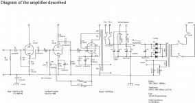
So I see from https://www.lundahltransformers.com/easy-to-build-se-amplifier/ there is a 300B schematic with adjustable global negative feedback.
I understand the basics of gnf, In this layout, I mostly understand the 100k log pot but the 150k/12pc in series looses me a little. Im guessing the RC circuit
simply prevents zero feedback and the cap has something to do with (reflected?) impedance..
That said, Id like to modify my already modified 300B amp. I added spst switches to both my global and local feedback loops.
In all honesty, with the speakers I have and volumes I listen too, no feedback anywhere opens the sound-stage and makes the music almost transparent.
Sure, in the original position (with feedback) and much higher listening levels, the sound is certainly more tight and controlled but that accounts for only .02% of my time..
The down side, at very low listening levels I get the dreaded hum while only listening to the turntable. (definatley 120hz, and a tad sharper than sine...)
Moving the volume a pinch louder lessens the hum either by drowning it out or changing something in circuit, or both.
I plan on trying to find the source of this hum, but I should have thought the original mod through a little more. I should have added a way to adjust the feedback.
Does anyone have any examples / snippets so I can cobble together a possible mod that might work with my system ?
Attachments
AudioFanMan,
If I understand it correctly, you have at least two problems.
1. Your amplifier has hum at the output.
Read the *** below, then,
Can you carefully measure the amount of ripple voltage that is across your 300B filaments? This is a floating measurement, you can not use a scope to do this. Use a sensitive DMM.
Can you carefully measure the amount of ripple of the B+ that connects to the output transformer?
What is the amount of the hum across the loaded secondary?
Now, ground the 300B grid, and measure make the same measurement across the loaded secondary, how does it compare?
2. You want to adjust the negative feedback of your 300B amplifier.
You need to approach these as separate problems.
Please post the complete schematic of your amplifier, if it is not the Yaqin 300B schematic ***.
Otherwise it is real hard to give advice, or to solve the problems you have.
Depending on where the negative feedback is, and where the source(s) of the hum is, adjusting the negative feedback value will change the level of the hum, or not change the level of the hum.
Just my opinions
Last edited:
Understood, and agreed. That said while I source, order and wait for whatever I need to make feedback adjustable, I could work on the hum...AudioFanMan,
If I understand it correctly, you have at least two problems.
2. You want to adjust the negative feedback of your 300B amplifier.
You need to approach these as separate problems.
Please post the complete schematic of your amplifier, if it is not the Yaqin 300B schematic ***.
Just my opinions
I do have an o-scope, and thank you much for the troubleshooting steps above.. Greatly appreciated...
Right this second, the garage workbench is a toasty 9 deg f, so I will probably wait untill its at least another 24 degrees... just to get above freezing!
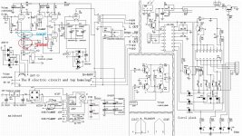
The posted 300B schematic IS my amp.
Here's what I did in an R120 SE amp:

http://www.pmillett.com/r120_se_amp.html
No attempt to compensate for the changes in gain...
Pete
http://www.pmillett.com/r120_se_amp.html
No attempt to compensate for the changes in gain...
Pete
Awesome, ty...Here's what I did in an R120 SE amp:
View attachment 1015255
http://www.pmillett.com/r120_se_amp.html
No attempt to compensate for the changes in gain...
Pete
So, to be sure Im guessing that R8 is mostly how your doing it ?
Again, Im very new to this but it looks like R4 and R9 is some sort of divider, raising R8 above 0v ??
If there was no selector would R9 simply be 402 and 681 ohms ?
May be if there was a schematic of this exact amp without adjustable feedback, i might better understand it all....
I see through a but of investigating the original amp you wrote about..

It looks like you added another 400 ohms with R9...
AHHHHHH I think I get it...
You chose the 400 ohms because the pot was 383 ohms???
If I have the basics, I need to understand how R2 and C2 are determined.
If I dont have the basics, please lmk ....
It looks like you added another 400 ohms with R9...
AHHHHHH I think I get it...
You chose the 400 ohms because the pot was 383 ohms???
If I have the basics, I need to understand how R2 and C2 are determined.
If I dont have the basics, please lmk ....
I should have kept reading your site!!Here's what I did in an R120 SE amp:
View attachment 1015255
http://www.pmillett.com/r120_se_amp.html
No attempt to compensate for the changes in gain...
Pete
This lets me know I was in fact on the right path ;-)
PM to you sent!
In every example I see, there is a resistor and low value capacitor in parallel. Above in pmillett's R120 amp, R2 1.21k ohms and C2 3.3nF on the global feedback...
Im pretty sure R2 is there to reduce the voltage since the 1st stage needs so little signal, but am not sure why there is the 3.3nF cap ?
Im pretty sure R2 is there to reduce the voltage since the 1st stage needs so little signal, but am not sure why there is the 3.3nF cap ?
C4 bypasses R4 for audio. In the A1 position, gain is set to minimum which is determined by the ratio of R2 to R9. Positions A2 thru A5 add resistance in parallel with R9 which reduces NFB and therefore increases gain. Provided the amp is stable in the A1 position it will be stable in all the other positions. There may also be some small alteration to the open loop gain because the gain of the EF37A depends to some extend on the ratio of R3 to R9 (and whatever is in parallel with it) but this depends on the gm of the EF37A at its operating point. Either way, it only aids stability so it is a "good thing".Awesome, ty...
So, to be sure Im guessing that R8 is mostly how your doing it ?
Again, Im very new to this but it looks like R4 and R9 is some sort of divider, raising R8 above 0v ??
If there was no selector would R9 simply be 402 and 681 ohms ?
May be if there was a schematic of this exact amp without adjustable feedback, i might better understand it all....
Cheers
Ian
- Home
- Amplifiers
- Tubes / Valves
- Examples of adjustable GNF ?