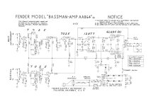
I have a 1967 black panel Bassman that appears to have been modified several times over the years. Since the circuit is far from original anyway, I figure I may as well set it up the way I want. The power section, from the PI on, is currently an AA864 circuit (schematic attached), which I intend to keep. I'm converting the "bass instrument" channel to a Marshall JTM45 preamp (details not important here). So, I thought it might be nice to turn the disconnected ground switch into a NFB switch that lets me choose between the stock AA864 NFB loop, and the greater level of feedback used in the JTM45.
My worry is the size of the resistors involved in the AA864 NFB loop. The NFB resistor is 820R, and connects at a point between the PI tail resistor and a 100R resistor to ground. I measure 0.4V there (other side of the 820R from the speaker). My first thought to get the right amount of NFB to match a JTM45 would be to have the switch connect a 330R resistor in parallel across the 820, getting ~220 ohms. (If you know how transformer taps affect negative feedback, maybe you can check my math: JTM45 has a 5k:27k voltage divider from the 16 ohm tap, I'm aiming for a similar amount of feedback using a 100:220 divider from the 4 ohm tap.) But that's a small enough value to make me worry a little about exposing the speaker to DC from that 0.4V node.
If I'm calculating correctly, the amp in its current form should be putting about 0.5mA through the 4 ohm speaker coil. Using a dummy load with my modification, I get 0.31V at the tail junction, so I think it will be putting more like 1.4mA through the speaker. I'm thinking that will be okay, but is there anything I'm missing here? Am I thinking about this the right way?
Attachments
Last edited:
As I understand it the JTM45 is nearly an exact copy of the 5F6-A Tweed Bassman not this one.
The preamp is two triode gain stages followed by a cathode follower to the tone stack that drives
the power amp. It seems to me that it would make a lot of sense to use a MOSFET in place of the
cathode follower.
You can see a discussion of it here with schematics and many mods including the switch you are talking about:
https://robrobinette.com/5F6A_Modifications.htm
It should also be noted that most are reporting that the 5F6-A are not built per the schematic, there are
a few values that changed in production and some changes around the Presence control.
It is interesting that the JTM45 was nearly an exact copy of the schematic not what Fender actually built.
Last edited:
My Bassman's preamp was mostly the AB165 circuit, which has one spare 12AX7 triode, so I've used that for the cathode follower. What I'll end up with is an AA864 power amp, an AB165 Normal channel preamp (a popular combination among techs apparently), and a JTM45 preamp in place of the Bass Instrument channel. The AA864 power section is mostly the same as a JTM45 except for the feedback loop, so with the NFB ratio matching, it should be somewhat similar.
I suppose I could increase the feedback resistor values like the examples on Robinette's site, but I like the idea of having stock AA864 values when the switch is disengaged, and I suspect my current plan is okay. I'm just worried there might be some aspect of these small feedback resistor values that I don't understand. I'm not sure why Fender chose to go from the 27k feedback resistor in the 5F6-A to the much smaller 820R resistor in the AA864 so maybe there's some other interaction that I'm not considering.
I suppose I could increase the feedback resistor values like the examples on Robinette's site, but I like the idea of having stock AA864 values when the switch is disengaged, and I suspect my current plan is okay. I'm just worried there might be some aspect of these small feedback resistor values that I don't understand. I'm not sure why Fender chose to go from the 27k feedback resistor in the 5F6-A to the much smaller 820R resistor in the AA864 so maybe there's some other interaction that I'm not considering.
Most of the current you're worried about will go through the output transformer secondary, not the speaker. The Hammond 1750L has a secondary DCR of only 170mΩ. I imagine the stock OT is similar. Using 170mΩ secondary DCR, 3.2Ω speaker DCR, and your 0.31V tail measurement, the DC offset through the speaker would be about 0.23mV or 0.07mA with a 220Ω feedback resistor.
Ah, indeed, I'm measuring ~240mΩ across the OT secondary. I guess that alleviates that worry! Thanks.
I'm left wondering how these feedback resistor values were chosen in the first place. Why start at 27k, and with that working fine, why switch to 820R?
I'm left wondering how these feedback resistor values were chosen in the first place. Why start at 27k, and with that working fine, why switch to 820R?
Notice how the feedback resistor is connected to a 100 ohm resistor to ground? It's similar to what was done to the Champ AA764, where they use a smaller feedback resistor connected to a series-to-ground resistor. It allows things like bypassing the cathode resistor at the same time as introducing feedback.
On the other desings (5F6-A) with the 27k feedback resistor, it'd go to the same node, but there's a 5k presence pot there instead of the 100R.
I'm not versed in the intricacies of negative feedback tube circuits, but if I were to guess, it's probably something about maintaining the same reflected impedance to achieve the same amount of feedback.
- Home
- Live Sound
- Instruments and Amps
- Even smaller NFB resistor on a Bassman AA864