A companion application to my other post titled Hi Voltage Discrete OpAmp application idea.
The 990Enh-Ticha discrete opamp is the heart of the high voltage front-end amplifier shown in pdf attachment below. This application was designed to drive a valve based output stage running on high voltage supply rails. It would work just as well driving a wall of FETs or bank of transistors. The reader is encouraged to examine Sonic Imagery Labs AN-10 to gain insight on how one can also provide Vcc and Vee to the 990Enh-Ticha discrete opamp from high voltage supply rails without the need to add additional low voltage power supplies to support front-end circuitry.
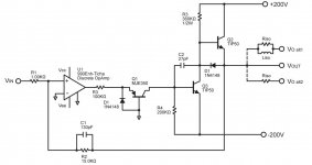
The output of the 990Enh-Ticha discrete operational amplifier (U1) creates a proportional current drive through the common base connected transistor Q1 to the base of Q3. Transistor Q3 forms a Class A amplifier with bias resistor R5, and transistor Q2 is simply an emitter follower used for output current boost. Overall voltage gain of this stage is set by the ratios of R2 divided by R1. In this case, the circuit shown has 23.5dB of voltage gain. The values of R1 and R2 where chosen to keep circuit thermal noise low and allow a small value capacitor to set the high frequency cutoff point.
C1 and C2 set the the upper bandwidth 3dB point at 175kHz. There will be 1-2 dB of peaking at 100-120kHz but careful tweaking of C1 and C2 could flatten this out. C1 and C2 should have high working voltages. Polypropylene or COG/NPO dielectric type capacitors are recommended since they have low voltage coefficients, good dissipation factors, and low dielectric absorbtion.
Riso/Liso or simply Riso may be necessary to prevent oscillation caused by the capacitive loading on the output of the amplifier.
Power supply decoupling capacitors are not shown in the circuit diagram for operational clarity. Low ESR electrolytic capacitors on the supply rails to ground are highly recommended. The 990Enh-Ticha opamp has 0.1uF capacitors at its VCC and VEE pins internally.
Frequency and phase response plots are shown in Figures 2. and 3 of Sonic Imagery Labs AN-11. Additional consideration should be given to the closed loop frequency response of U1 if the designer is to radically increase or decrease the overall gain of this stage.
A final note. The voltages used in this circuit are high and can be quite dangerous. A certain level of situational awareness should be exercised at all times to maintain personal safety and prevent damage to components and test equipment.
The 990Enh-Ticha discrete opamp is the heart of the high voltage front-end amplifier shown in pdf attachment below. This application was designed to drive a valve based output stage running on high voltage supply rails. It would work just as well driving a wall of FETs or bank of transistors. The reader is encouraged to examine Sonic Imagery Labs AN-10 to gain insight on how one can also provide Vcc and Vee to the 990Enh-Ticha discrete opamp from high voltage supply rails without the need to add additional low voltage power supplies to support front-end circuitry.
The output of the 990Enh-Ticha discrete operational amplifier (U1) creates a proportional current drive through the common base connected transistor Q1 to the base of Q3. Transistor Q3 forms a Class A amplifier with bias resistor R5, and transistor Q2 is simply an emitter follower used for output current boost. Overall voltage gain of this stage is set by the ratios of R2 divided by R1. In this case, the circuit shown has 23.5dB of voltage gain. The values of R1 and R2 where chosen to keep circuit thermal noise low and allow a small value capacitor to set the high frequency cutoff point.
C1 and C2 set the the upper bandwidth 3dB point at 175kHz. There will be 1-2 dB of peaking at 100-120kHz but careful tweaking of C1 and C2 could flatten this out. C1 and C2 should have high working voltages. Polypropylene or COG/NPO dielectric type capacitors are recommended since they have low voltage coefficients, good dissipation factors, and low dielectric absorbtion.
Riso/Liso or simply Riso may be necessary to prevent oscillation caused by the capacitive loading on the output of the amplifier.
Power supply decoupling capacitors are not shown in the circuit diagram for operational clarity. Low ESR electrolytic capacitors on the supply rails to ground are highly recommended. The 990Enh-Ticha opamp has 0.1uF capacitors at its VCC and VEE pins internally.
Frequency and phase response plots are shown in Figures 2. and 3 of Sonic Imagery Labs AN-11. Additional consideration should be given to the closed loop frequency response of U1 if the designer is to radically increase or decrease the overall gain of this stage.
A final note. The voltages used in this circuit are high and can be quite dangerous. A certain level of situational awareness should be exercised at all times to maintain personal safety and prevent damage to components and test equipment.