I'm a noname here, but I've been working on a DAC design over at diymobileaudio.com for a while now. Here's the link to the post where I described all the important design details: DIYMA Car Audio Forum - View Single Post - 2011 MINI Cooper CarPC Build
Here's a really quick summary:
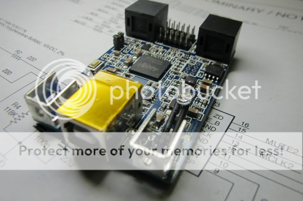
Here's a picture of the MiniDSP USBStreamer, 10-channel USB-to-I2S converter. The yellowish stuff on the USB connector is a piece of insulating Kapton tape.
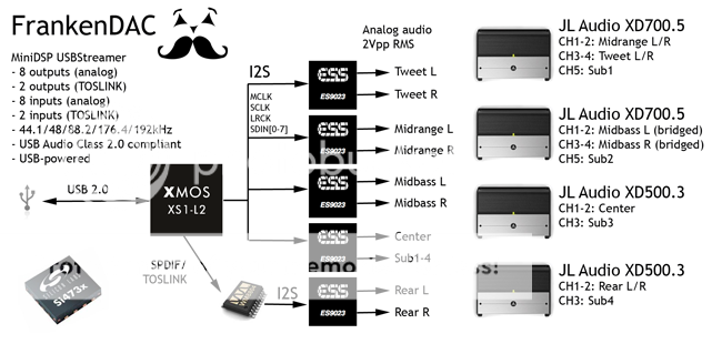
Here's the original block diagram that I proposed back on October 31:
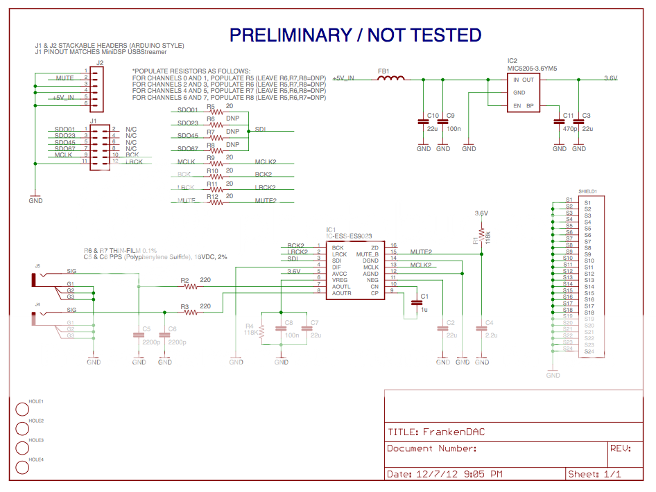
Here's the schematic of the DAC PCB. I decided on the ESS9023P DAC chip because of the low-parts count, i.e. the KISS approach. Keep in mind that there will be five of these boards stacked on top of each other (for a total of 10 channels) to complete the final design.
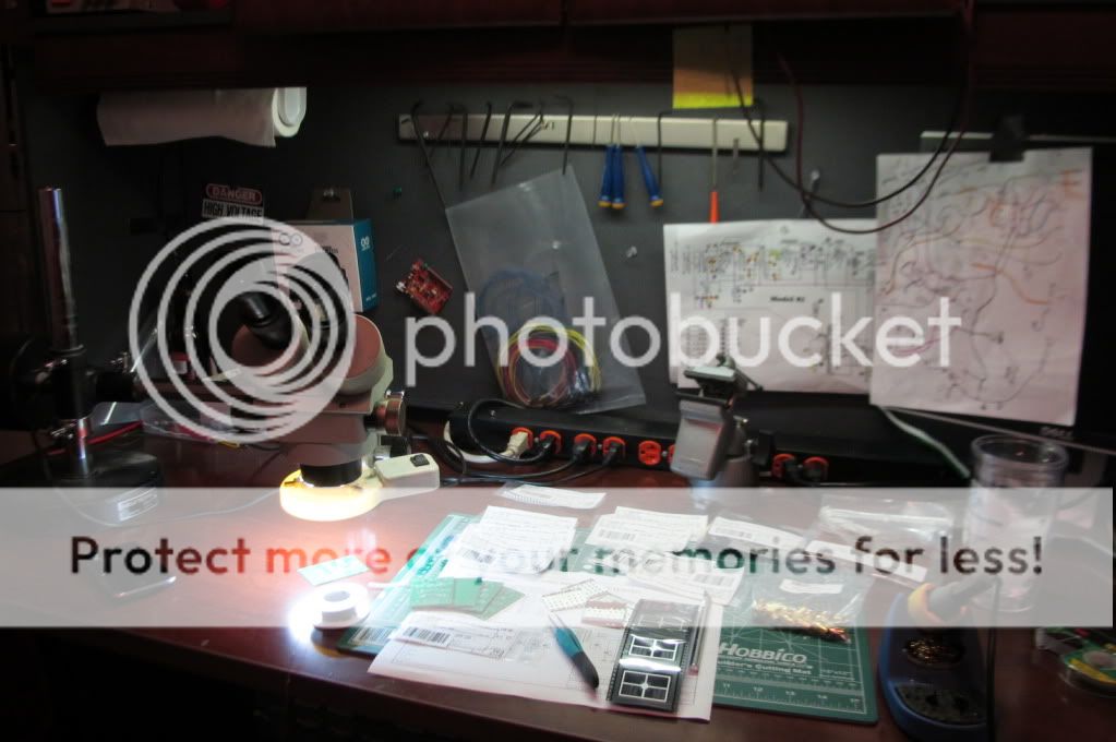
Beginning of the build phase:
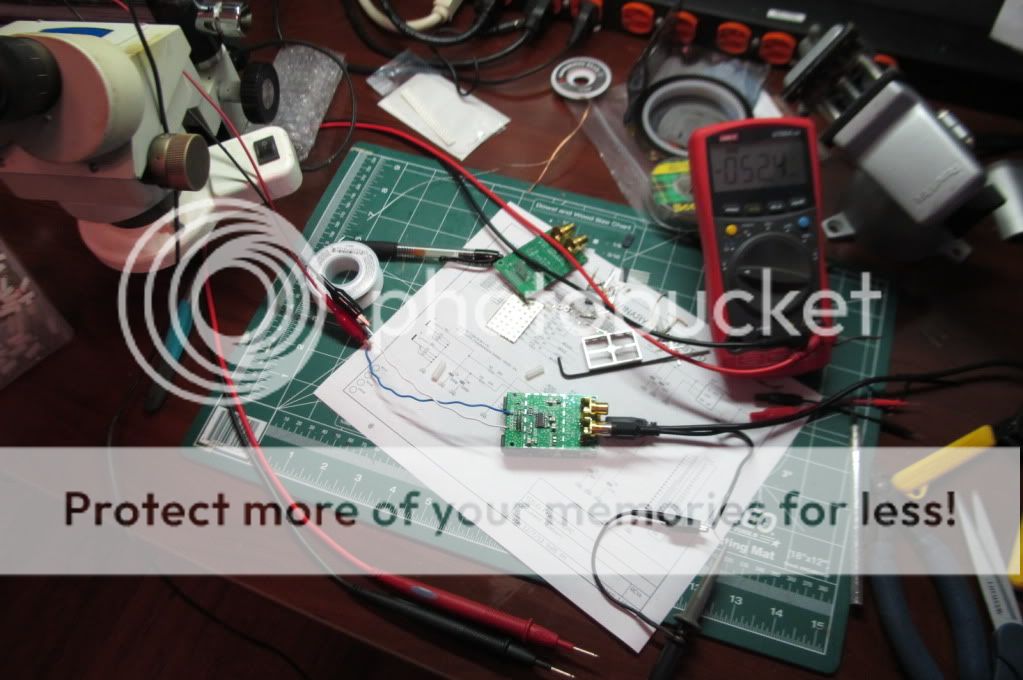
Powering up for the first time. Checked the voltage regulator output voltage, and a few other test points.
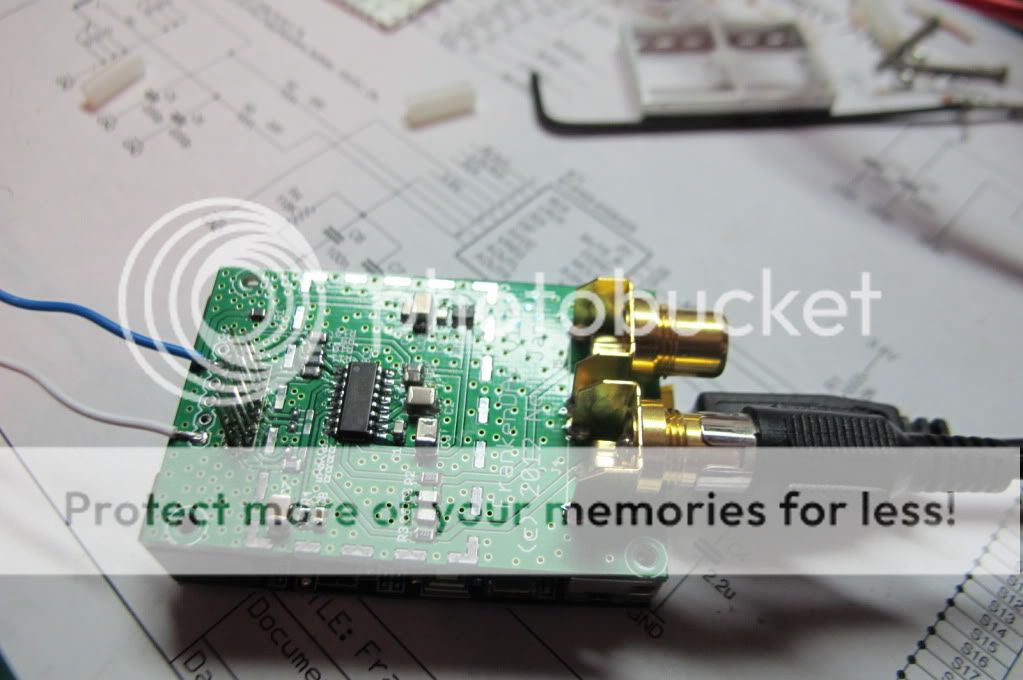
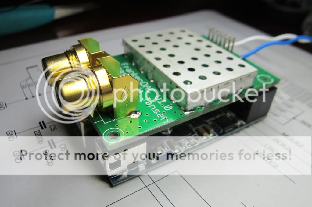
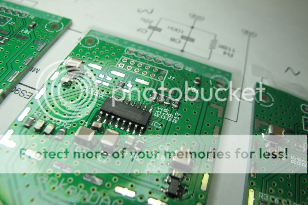
A close-up shot of the first board while powered up and playing a 1 kHz sine wave. Disregard the flux and wire leads sticking out, those will be gone after the testing phase.
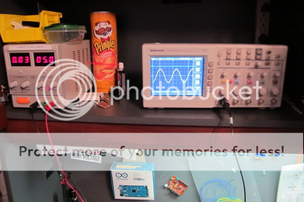
Here's the 1 kHz sine wave coming out of the DAC, and the 5V lab supply:
Next step was to install the EMI fence. As mentioned earlier, this is a faraday cage to keep out the nasty electromagnetic radiation that plagues my BMW-designed car 😛
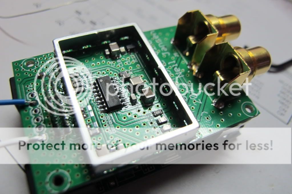
Now with the EMI fence's "lid" installed.
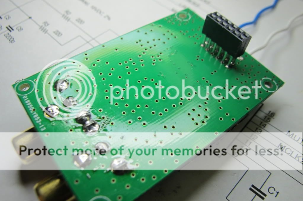
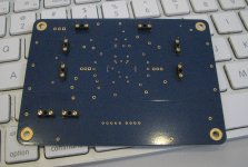
The bottom of the PCB is a solid ground plane. I've never really seen a DAC that managed to have this before. RF guys use this technique religously, but consumer electronics do not (ever). A solid ground plane does many things for a pcb layout: It acts as a faraday cage for stray EMI (in both directions, i.e. radiated and susceptibility). It provides a quick "return path" for high-speed RF signals (keep in mind that my I2S clock lines are ~24 MHz with VERY high rise times. Any upset here will cause EMI and worse yet, jitter problems. Lastly, the solid ground plane provides a very beefy ground system with extremely low resistance, so that every point on the pcb seems the same ground potential (same reason you guys use beefy ground wires on your amps 😎 ). The holes on the board are "vias", they're plated copper and pass the ground plane to the front side of the board (but you guys already knew that, right?? 😎 )
One more shot of the first guinea pig board.
Component assembly of the remaining four boards:
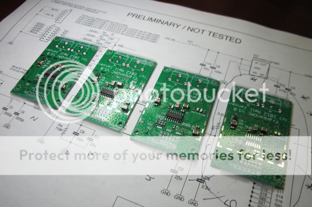
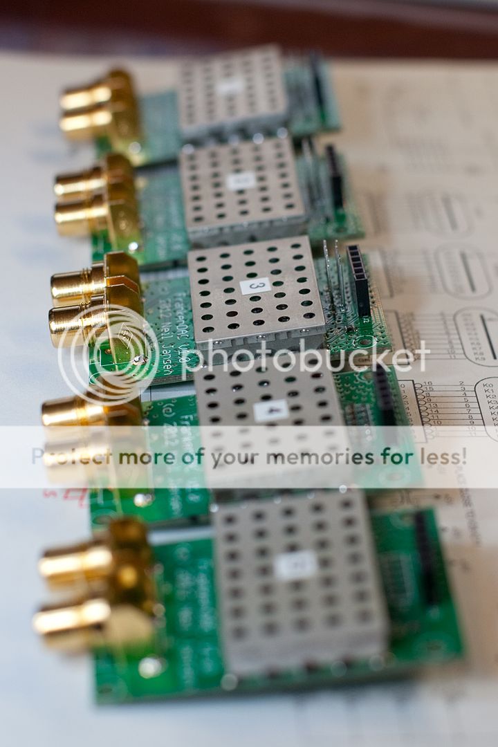
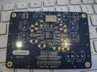
Each module is conveniently labeled 1 through 5:
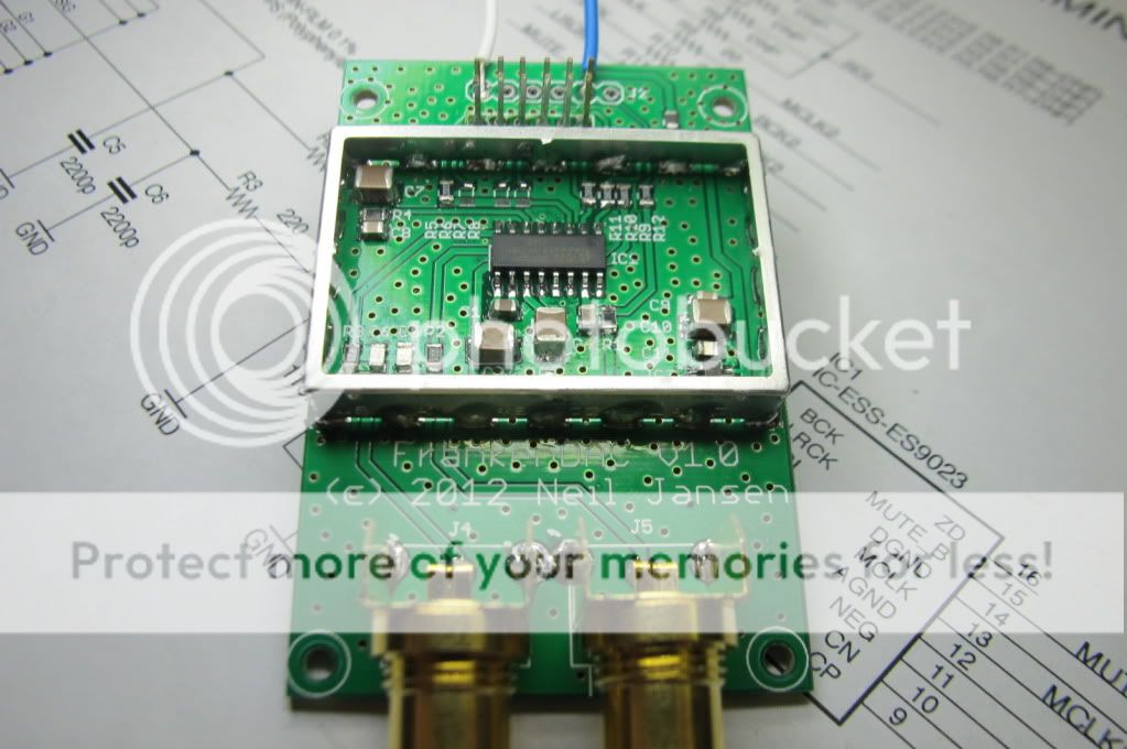
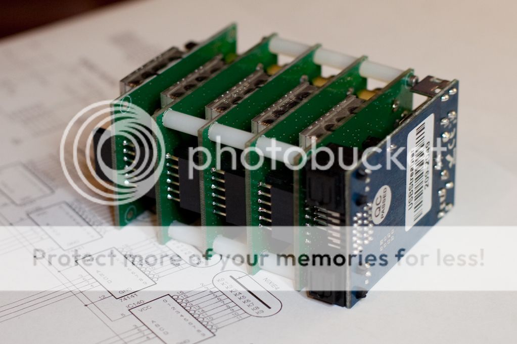
Here's the complete assembly, from the back. Notice the TOSLINK in and out connectors on the MiniDSP USBStreamer, and the connectors that pass the signals back and forth between the modules.
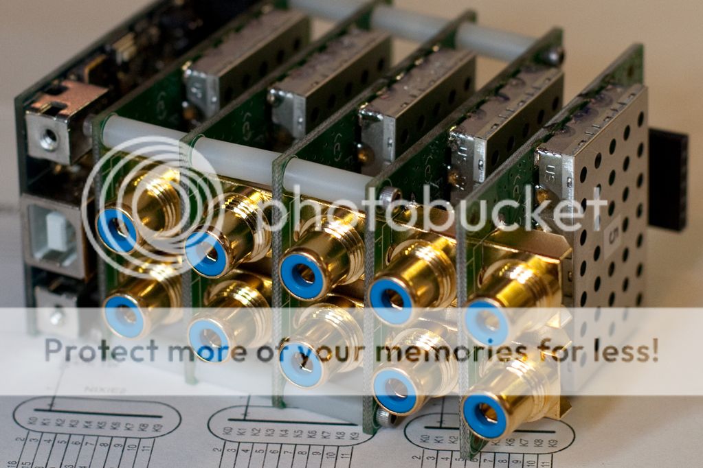
And finally, a shot from the front. Next step is to design and fabricate a nice metal enclosure for the whole thing to sit in.
Channel 1 thru 8 have been tested and are working. Channels 9 and 10 still require a TOSLINK-to-I2S bridge to squeeze the maximum 10 channels out of the MiniDSP USBStreamer. For this, I'm planning on hacking up the $25 FiiO D3, as described by the Hifiduino blog.
I'd love to hear questions / comments / suggestions. Also, I have five boards left over if anyone is interested 🙂
Here's a really quick summary:
- This is a custom-designed 10-channel DAC to interface my Mac Mini CarPC, to date I've not seen anything remotely like it. I designed the circuit (with a bit of borrowing from existing designs out there), sourced the component parts, did the printed circuit board layout, and then built the board assemblies.
- This is a no-compromise SQ design. I wasn't content with just using off-the-shelf equipment from a Sweetwater Music catalog. I'm looking for very high SNR numbers to my amplifiers, to get a great dynamic range (my amps will likely be modded too). I will be attempting to compete with this system in March at the IASCA spring break nationals (and the MECA event there as well). Hopefully I can get my acoustic issues fixed by then.
- I'm using the MiniDSP USBStreamer (image below) as my USB-to-I2S bridge (I2S being the most common electrical protocol that audio DAC chips use). This component is responsible for virtually all of the jitter (or lack of it), since it's providing all of the clocking signals to the DAC.
- Rather than use an expensive and complicated 8+ channel DAC chip, I decided to use individual low-cost stereo DAC chips and go with a "stacking" design. The clock signals are "fanned out" to the individual boards (with care taken to route the traces properly and prevent signal reflection. This design allowed me to do a lot of pcb layout tricks where I could keep all of the clock and analog signals guarded with a ground trace (which prevents signal crosstalk), and keep an uninterrupted ground plane (which prevents a lot of nasty EMI and other bad stuff from happening).
- Total cost of the DAC project so far is $89 in component parts, $2.50 each for the custom circuit boards, and $145 for the MiniDSP USBStreamer. That's less than a lot of the shitty pro-audio equipment, and I'll hopefully have better specs....
Here's a picture of the MiniDSP USBStreamer, 10-channel USB-to-I2S converter. The yellowish stuff on the USB connector is a piece of insulating Kapton tape.
Here's the original block diagram that I proposed back on October 31:
Here's the schematic of the DAC PCB. I decided on the ESS9023P DAC chip because of the low-parts count, i.e. the KISS approach. Keep in mind that there will be five of these boards stacked on top of each other (for a total of 10 channels) to complete the final design.
- J1 is the connector to the MiniDSP USBStreamer. Each board can be configured to route either of the four I2S streams to the chip, via R5-R8.
- J2 is the power header and mute circuit.
- J4 is the right RCA output.
- J5 is the left RCA output.
- IC1 is the DAC chip, the ESS ES9023P. It's specs are pretty good, but chip specs aren't as important as getting the board layout and component part selection right.
- IC2 is a 3.6V low-dropout ultra-low-noise voltage regulator. I love Linear Technology parts, but they think their **** doesn't stink and therefore have very high prices; I opted to use the Micrel MIC5205-3.6YM5 instead (as have a few other hobby DAC designs).
- SHIELD1 is an EMI shield (i.e. a faraday cage).
- FB1 is a ferrite bead, which is used as an input EMI filter to the power supply.
- You guys know what resistors and capacitors do hopefully, no need to explain those :laugh:
Beginning of the build phase:
Powering up for the first time. Checked the voltage regulator output voltage, and a few other test points.
A close-up shot of the first board while powered up and playing a 1 kHz sine wave. Disregard the flux and wire leads sticking out, those will be gone after the testing phase.
Here's the 1 kHz sine wave coming out of the DAC, and the 5V lab supply:
Next step was to install the EMI fence. As mentioned earlier, this is a faraday cage to keep out the nasty electromagnetic radiation that plagues my BMW-designed car 😛
Now with the EMI fence's "lid" installed.
The bottom of the PCB is a solid ground plane. I've never really seen a DAC that managed to have this before. RF guys use this technique religously, but consumer electronics do not (ever). A solid ground plane does many things for a pcb layout: It acts as a faraday cage for stray EMI (in both directions, i.e. radiated and susceptibility). It provides a quick "return path" for high-speed RF signals (keep in mind that my I2S clock lines are ~24 MHz with VERY high rise times. Any upset here will cause EMI and worse yet, jitter problems. Lastly, the solid ground plane provides a very beefy ground system with extremely low resistance, so that every point on the pcb seems the same ground potential (same reason you guys use beefy ground wires on your amps 😎 ). The holes on the board are "vias", they're plated copper and pass the ground plane to the front side of the board (but you guys already knew that, right?? 😎 )
One more shot of the first guinea pig board.
Component assembly of the remaining four boards:
Each module is conveniently labeled 1 through 5:
Here's the complete assembly, from the back. Notice the TOSLINK in and out connectors on the MiniDSP USBStreamer, and the connectors that pass the signals back and forth between the modules.
And finally, a shot from the front. Next step is to design and fabricate a nice metal enclosure for the whole thing to sit in.
Channel 1 thru 8 have been tested and are working. Channels 9 and 10 still require a TOSLINK-to-I2S bridge to squeeze the maximum 10 channels out of the MiniDSP USBStreamer. For this, I'm planning on hacking up the $25 FiiO D3, as described by the Hifiduino blog.
I'd love to hear questions / comments / suggestions. Also, I have five boards left over if anyone is interested 🙂
nice work mate! I really like it!; however you are far from the first dac designer on here or elsewhere to use a 'solid' ground plane.
Acko finished this design over 2 years ago and the previous gen (without the w.fl connectors and rogers teflon board) was before that. its all gnd plane underneath there, but has guides (kinda segmented but its all continuous if you know what I mean) to help keep loop area small. its an ES9012 dac. 100MHz clocks =) bulk polymers arent fitted on this one yet as you can see. the headers underneath are for stacking on the reg board
one thing, just wondering, you arent worried about the dacs at the top getting a signal thats been through the impedance ringer vs the bottom one? is each i2s signal paired with a ground pin on that super long header? do you have any type of buffer driving the dac outputs?
soz, you did call for comments 😉
love the RF guard, can I ask where you got them? very cute little boards, not in need of another dac, but i'm sure you'll get some takers. I was thinking of putting something like that on an ES9016 dac design i'm playing with.
Attachments
Last edited:
Thanks for the comments. The RF fences were from Digikey, I believe the manufacturer is Laird Technologies. Pretty cheap and easy to work with. I really don't think they're overkill, especially in an EMI-rich environment such as a new BMW-designed car.nice work mate! I really like it!; however you are far from the first dac designer on here or elsewhere to use a 'solid' ground plane.
Acko finished this design over 2 years ago and the previous gen (without the w.fl connectors and rogers teflon board) was before that. its all gnd plane underneath there, but has guides (kinda segmented but its all continuous if you know what I mean) to help keep loop area small. its an ES9012 dac. 100MHz clocks =) bulk polymers arent fitted on this one yet as you can see. the headers underneath are for stacking on the reg board
one thing, just wondering, you arent worried about the dacs at the top getting a signal thats been through the impedance ringer vs the bottom one? is each i2s signal paired with a ground pin on that super long header? do you have any type of buffer driving the dac outputs?
soz, you did call for comments 😉
love the RF guard, can I ask where you got them? very cute little boards, not in need of another dac, but i'm sure you'll get some takers. I was thinking of putting something like that on an ES9016 dac design i'm playing with.
As for the signal ringing on the I2S fanout, the distances are so small, I wasn't going to worry about it. I'm not an RF guy, if it does add measurable jitter, I can always snip the appropriate pins on the stackable headers to remove the stub(s). Each line has a series 20 ohm resistor at the DAC. Another mod I was going to make was a voltage divider for each signal with the divider voltage at the logic low-to-high transition point, which I've been told can reduce jitter. At this point, I'm still waiting to do a full set of measurements on a good spec an, and a formal listening test.
No tech eval but ...
Just Awesome! Nice designs, hard work, great layout, sweet stacking, the shield ... well done, sir. A beautiful implementation of miniDSP!
Can you tell us more about this channel 9,10 toslink issue?
Cheers,
Jeff
PS You even take good pictures!
Just Awesome! Nice designs, hard work, great layout, sweet stacking, the shield ... well done, sir. A beautiful implementation of miniDSP!
Can you tell us more about this channel 9,10 toslink issue?
Cheers,
Jeff
PS You even take good pictures!
Last edited:
The MiniDSP USBStreamer provides 8 channels of I2S via the 2mm rectangular header, and then an additional two channels via fiber optic TOSLINK connector. I do need those extra two channels, so I've really got two choices: (A) make my own circuit board with a TOSLINK connector, a WM8804 or similar SPDIF to I2S chip, and a connector for the DAC board, or (B) modify something that already exists.Can you tell us more about this channel 9,10 toslink issue?
The FiiO D3 is a Chinese consumer-grade DAC that has a TOSLINK fiber optic input, an SPDIF to I2S converter chip, and a complete DAC chip and glue circuitry, with RCA outs. The Hifiduino blog linked above showed a lot of the details, you can get right at the I2S signals, disconnect the FiiO built-in DAC, and run your own DAC board. It's just as pictured in my block-level diagram above, except instead of a WM8804, they use a Cirrus Logic chip now, I believe.
I'm not too concerned about jitter or the relative delay between CH.9&10 and the other channels, as they're being used for rear fill and don't have to correlate with the other channels at all, and I also have the added bonus of time correction in my CarPC DSP code. I would probably be ok with using just the FiiO DAC as-is, and will likely go that route at first; jitter will not be improved much if any (depending on how much ESS marketing Kool Aid you believe), but will improve SNR by quite a bit (which is very important in the level of competition I'm attempting, you can lose points for audible noise floor).
I'm watching this, appreciatively.
I can't help with tech, but could well dip into the wallet when time comes. I have been trying to find a way to use the USBstreamer in this fashion; this would be my solution.
cheers
I can't help with tech, but could well dip into the wallet when time comes. I have been trying to find a way to use the USBstreamer in this fashion; this would be my solution.
cheers
As mentioned already in the miniDSP Forum: Great work! And I also like your pictures. Not that easy to take good pictures of circuit boards with their reflecting surfaces😉
Really like the layout, the compact stacked design and especially the RF Fences 🙂
Can you please tell me what I2S signal buffer is used on the miniSTREAMER?
What was the reason for changing the original output LP Filter (4,7nF [F3:141kHz] -> 220Ohm + 2200pF [F3:157kHz?])? And what is the exact value of the ferite bead used to decouple power line?
Best regards, Daniel
Probably just the XMOS ASIC chip itself. I didn't want to use a crazy system of buffers, instead I used the KISS approach, payed great attention to board routing and high-speed layout, and kept the trace lengths very short.Can you please tell me what I2S signal buffer is used on the miniSTREAMER?
Because the ODAC used those values, I'm taking NwAvGuy's word since he's done more real-world testing than I'm able to. My project is non-commercial and I've credited him for a lot of my inspiration for this project, so I'm hoping he won't mind 🙂What was the reason for changing the original output LP Filter (4,7nF [F3:141kHz] -> 220Ohm + 2200pF [F3:157kHz?])? And what is the exact value of the ferrite bead used to decouple power line?
The ferrite bead is Digikey P/N 240-2399-1-ND, $0.07 USD. It has pretty generic specs, I selected it based off of availability and price.
hey, Im very impressed by this! great idea
Im actually wanting to do almost the opposite, the outputs are useful but I need atleast 4 to 10 inputs of analog audio to multitrack record to the PC.
Could anyone point me in the right direction on how to get USBStreamer set up like that? or anyone else doing this
Im actually wanting to do almost the opposite, the outputs are useful but I need atleast 4 to 10 inputs of analog audio to multitrack record to the PC.
Could anyone point me in the right direction on how to get USBStreamer set up like that? or anyone else doing this
Also, I have five boards left over if anyone is interested 🙂
Great project. I would like to buy the boards.
PM to me if available to send to Hong Kong.
Thank you.
There are not so many ADC projects here on DIYaudio and also elsewhere. Most ADCs have SPDIF outputs and to get I2S you'd need to tap those signals somewhere on the board. Of course it also depends on your budget.
Probably the best way will be using some eval boards, e.g. PCM4204 Evaluation Module (EVM) - PCM4204EVM - TI Tool Folder 4ch ADC or PCM4222 Evaluation Module (EVM) - PCM4222EVM - TI Tool Folder 2ch ADC. Those are around 150$ each though...
hope this helps...
Probably the best way will be using some eval boards, e.g. PCM4204 Evaluation Module (EVM) - PCM4204EVM - TI Tool Folder 4ch ADC or PCM4222 Evaluation Module (EVM) - PCM4222EVM - TI Tool Folder 2ch ADC. Those are around 150$ each though...
hope this helps...
hey, Im very impressed by this! great idea
Im actually wanting to do almost the opposite, the outputs are useful but I need atleast 4 to 10 inputs of analog audio to multitrack record to the PC.
Could anyone point me in the right direction on how to get USBStreamer set up like that? or anyone else doing this
Hey, Thankyou thats great, am i right in saying if a DAC baord has SPDIF it will have somewhere a I2S signal, or do I have to investigate further to find out.
I am not very knowledgeable on those things but i think id be able to do this
I guess the reason theres not man ADC projects is because nobody realy needs that many inputs unless they are recording bands. or taking inputs to be processed.
I am not very knowledgeable on those things but i think id be able to do this
I guess the reason theres not man ADC projects is because nobody realy needs that many inputs unless they are recording bands. or taking inputs to be processed.
Hey, Thankyou thats great, am i right in saying if a DAC baord has SPDIF it will have somewhere a I2S signal, or do I have to investigate further to find out.
Its not that easy
 It depends on the actual implementation. There are codecs (ICs) with integrated SPDIF transceiver and in this case you wont be able to grap the signals. If there is a dedicated SPDIF transmitter on board (e.g. WM8804) I2S will probably be used to connect ADC and transmitter, however you can still not be sure that the actual configuration fits to the needs of the USBStreamer.
 Thus best would indeed be to use the eval boards since they can be configured according to your needs. Or you simply use a multichannel sound card 😱
And finally, a shot from the front. Next step is to design and fabricate a nice metal enclosure for the whole thing to sit in.
Love the stacking concept, and the EMI shields, looks very professional 🙂
Don't like the optical to I2S bridge, that feels iffy. At least take the 5V SPdif-like signal that feeds the optical module. Those 1-cent LEDs do a horrible job of transferring digital audio. Do you really need channel 9 and 10? Without I2S, it is impossible to keep channel 9 and 10 in sync with the other channels. Which is recipe for disaster for a multi-amp system.
The RCA connectors look very good, do you have a part number for those?
Keep up the good work!!!
I'm well aware of that, but luckily, for my application, it does not matter. In my original post on diyma, I explained that the last two channels (the ones that go through the toslink) are for rear channel surround, and are delayed by 20 milliseconds or so, and are therefore not correlated to the other channels. Here's the post from last January that included a system diagram:Love the stacking concept, and the EMI shields, looks very professional 🙂
Don't like the optical to I2S bridge, that feels iffy. At least take the 5V SPdif-like signal that feeds the optical module. Those 1-cent LEDs do a horrible job of transferring digital audio. Do you really need channel 9 and 10? Without I2S, it is impossible to keep channel 9 and 10 in sync with the other channels. Which is recipe for disaster for a multi-amp system.
The RCA connectors look very good, do you have a part number for those?
Keep up the good work!!!
DIYMA Car Audio Forum - View Single Post - 2011 MINI Cooper CarPC Build
The RCA connectors were from Parts Express as a buyout, I've no idea if they're still in stock. They didn't have white or black, so I went with blue 🙂
The RCA connectors were from Parts Express as a buyout, I've no idea if they're still in stock. They didn't have white or black, so I went with blue 🙂
They still have them in Red, Blue, Green and Yellow. No white or black unfortunately.
But minimum order for the Netherlands is 50 USD, and UPS shipment will be rather expensive...
I've never seen those PCB mount RCA connectors with a thread to bolt them to a chassis, that combo is very nice. Without bolting, the solder pads will be put to a lot of strain each time you pull out a connector.
Hi Neil_J
Very nice project, impressing work and compact design.
Could you tell us more about your "EMI fence" ?
Does someone have some feedback about using this kind of "Faraday cage" ?
Thanks
Phil
Very nice project, impressing work and compact design.
Could you tell us more about your "EMI fence" ?
Does someone have some feedback about using this kind of "Faraday cage" ?
Thanks
Phil
Hi Neil_J
Very nice project, impressing work and compact design.
Could you tell us more about your "EMI fence" ?
Does someone have some feedback about using this kind of "Faraday cage" ?
Thanks
Phil
You'll find them inside cell phones, radar detectors, GPS receivers, and any other device which needs a really low noise floor. You can buy them from Digikey, they're actually pretty cheap as long as you buy the super small ones like I did (custom ones will have a high non-recurring upfront cost for tooling and such). There are tons and tons of books and articles about EMI mitigation out there, I'm certainly not an expert but tried to use the "basics" in this design: solid ground plane on the bottom, liberal use of guard traces, lots of attention to routing for shortest trace lengths, using series resistors on the high-speed clock lines to prevent RF reflection, careful power supply design (e.g. "borrowing" proven designs already out there), and of course shielding the crap out of it. If you consider that most software radio transmitters have a final digital to analog stage (often called a DUC or digital upconverter), then you'll realize I'm not the first to try out these design techniques. But I may be the first to try it with an audiophile DAC, at least in the DIY community. Yea it might be overkill but what's the harm in that? 🙂
I had an error on my first run of boards where the RCA connectors were back too far to be able to panel mount. And furthermore, I've not found the hex nuts to screw them on yet (although I've not looked around that much, or even measured the threads).They still have them in Red, Blue, Green and Yellow. No white or black unfortunately.
But minimum order for the Netherlands is 50 USD, and UPS shipment will be rather expensive...
I've never seen those PCB mount RCA connectors with a thread to bolt them to a chassis, that combo is very nice. Without bolting, the solder pads will be put to a lot of strain each time you pull out a connector.
- Status
- Not open for further replies.
- Home
- Source & Line
- Digital Source
- ES9023 DAC design for MiniDSP USBStreamer