Hello all,
Can someone share schematic diagram of ensemble corifeo power amplifier.
Thanks in advance,
Yoram
Can someone share schematic diagram of ensemble corifeo power amplifier.
Thanks in advance,
Yoram
Let me know if you find one please
Looking for the diagrams of a Virtuoso as well...
Ensemble them selves are not so willing, but it must be said that these where made in France back then rather then current Swiss so must be a different company since then...
I'm on the hunt for schematics for years now, not been able to succeed and if we ever find one then the question raises whether it will be acc. to the schematics as the way its been build it looks like a experiment...
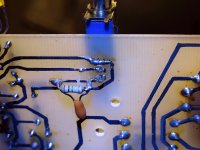
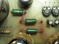
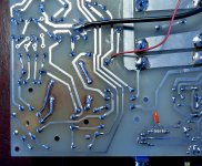
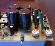
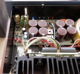
I had 3 resistors replaced (same value but 10W now) near the tubes as the originals where a bit too close to the (crappy) PCB and left burn marks over the years...
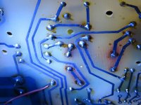
On top of that I had loads of bad solder joints on the PCB of both Pre and Power amp
Looking for the diagrams of a Virtuoso as well...
Ensemble them selves are not so willing, but it must be said that these where made in France back then rather then current Swiss so must be a different company since then...
I'm on the hunt for schematics for years now, not been able to succeed and if we ever find one then the question raises whether it will be acc. to the schematics as the way its been build it looks like a experiment...
I had 3 resistors replaced (same value but 10W now) near the tubes as the originals where a bit too close to the (crappy) PCB and left burn marks over the years...
On top of that I had loads of bad solder joints on the PCB of both Pre and Power amp
Attachments
-
 01 Ensemble Corifeo bad joints.jpg581.1 KB · Views: 148
 -
 02 Ensemble Corifeo Original resitors.jpg578.5 KB · Views: 145
 -
 03 Ensemble corifeo power - main board.jpg548.7 KB · Views: 138
 -
 04 Ensemble Corifeo new resistors.jpg714.6 KB · Views: 140
 -
 05 Ensemble Corifeo strengthen print.jpg696.9 KB · Views: 137
 -
 06 Ensemble Corifeo ner resistors installed.JPG637 KB · Views: 100
 -
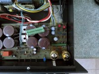
 07 Ensemble Corifeo finished.jpg594.8 KB · Views: 114
Last edited:
to my knowledge, there is no schema available for these devices, sorry
the best thing to do is to take a photo of the pcb from above and below and draw the circuit by hand, then connect each component and finally, propose reading the schema to those who understand and explain
the best thing to do is to take a photo of the pcb from above and below and draw the circuit by hand, then connect each component and finally, propose reading the schema to those who understand and explain
That is actually a good suggestion and I had that in mind already.
For the main board that isn't such a problem, the others however are a bit more tricky...
For the main board that isn't such a problem, the others however are a bit more tricky...
yes 🙁 but with patience all is possible 🙂the others however are a bit more tricky...
- Status
- Not open for further replies.