
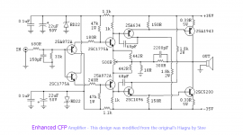
I can't see any CFPs in that circuit. Have they been 'enhanced' away? I can see an emitter follower, and a complementary feedback triple.
Why don't you tell us about your modifications first?
Why don't you tell us about your modifications first?
The name's "Hiraga" not "Hiagra".
...
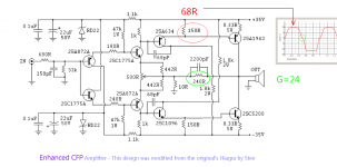
Indeed, needs work.this ideais NOT tested
...
Attachments
Looks like he started with Jean Hiraga's design (below), and broke it.Why don't you tell us about your modifications first?
Attachments
Yes.godfrey said:Looks like he started with Jean Hiraga's design (below), and broke it.
OK. The best help I can give is to suggest you read a good book on electronics (e.g. H&H), then read it again until you understand it.Stee said:please help me

+1 Agreed, unless Stee's contributions are intended as a joke. (Post 8 is ridiculous).The best help I can give is to suggest you read a good book on electronics (e.g. H&H), then read it again until you understand it.
The original Hiraga design uses CFP outputs for significant local negative feedback in the output stage. This is all but gone in this design, which would need to use a "real" Darlington config to work. I think both are current output...
Maybe things start working once the configuration is changed to a "classic" CFP setup, as shown e.g. here. This actually is the far more common version, a staple in compact hi-fi systems back in the day. I wonder which advantages the "inverted" output configuration chosen by Hiraga would have? Sure seems worth checking out. Looks like it's essentially the current output version, for better or worse.
Maybe things start working once the configuration is changed to a "classic" CFP setup, as shown e.g. here. This actually is the far more common version, a staple in compact hi-fi systems back in the day. I wonder which advantages the "inverted" output configuration chosen by Hiraga would have? Sure seems worth checking out. Looks like it's essentially the current output version, for better or worse.
Last edited:
That's a very interesting circuit, but there is no CFP in it.comes from MF XA schematic
🙂
Hiraga called the configuration of its output stage as Darlingnot (inverted Darlington) which is still wrong. It is a real CFP (or Sziklai pair) which can considered as a composite transistor, exploited here in common emitter configuration. As Godfey says, there is no CFP in Stee's circuit.
- Status
- Not open for further replies.
- Home
- Amplifiers
- Solid State
- Enhanched CFP amplifier