Thank you for coming. For the past six months I've been on the trail of a method of loading passive radiators with mass without having to actually load mass onto the passive diaphragm. As you know, passive radiators as a reflex-loading method differ from the typical reflex port in that above their tuning frequency, their group delay is lower, so the sound approaches that of a sealed box. Yet, at the tuning frequency, group delay is through the roof. I have a hypothesis that this dramatic peak in group delay at the tuning frequency of the passive radiator is because of the very large mass that is generally loaded onto passive radiators. Passive radiators have more parameters controlling their motion than a bass reflex port does, because a bass reflex port has no suspension system. On the other hand, a passive radiator has a surround and, in some cases, a spider.
I have, on hand, three really cheap crap passive radiators made by Pioneer. If I load mass onto the diaphragm itself, the diaphragm will sag or cantilever out of control. I recently saw some speakers made by VMPS Audio Products, of El Sobrante, CA. Their floorstanding speakers and subwoofers use a type of technology called a slot-loaded passive radiator for reflex loading. The passive radiator is relatively low in mass, and it fires downward into a cavity which is only open to the outside through a slot.
VMPS RM-40 Loudspeaker (2002 Best Of CES Winner)
Look at the base. In the very middle of the bottom panel of the loudspeaker, there is a 10" passive radiator.
VMPS Larger Subwoofer
Here, there is no baseplate. The slot is formed by the base and the floor. You can see that a single 15" passive radiator is used to load the two drivers, a 12" and a 15" woofer.
The passive radiator itself is simply a paper cone, with a spider and a surround, in a stamped steel basket. They do not seem to be massed very heavily at all, as evidenced by the fact that they can be used in a downfiring configuration and not sag out. This tells me that the mass-loading used to tune the passive radiator is contributed by the loading provided by the cavity into which the passive radiator fires and the ratio of diaphragm size of the passive radiator to that of the slot that is the opening to the outside.
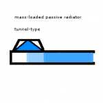
I have a different idea for adding the necessary mass to the passive radiator to tune it to the appropriate frequency. It involves coupling a passive radiator to a tunnel. A bass port is simply just a mass of air in a port. The tunnel will have the same cross-sectional area as the passive radiator, and will have a certain mass of air suspended in it. My hypothesis is that by this method, the driver will see the mass of air in the tunnel and the mass on the passive radiator as one mass. I've attached an image of what my idea looks like. I have shaded three areas: the passive radiator, and the tunnel. I am wondering, though, how much of the tunnel adds to the mass of the passive radiator. The darker shaded area of the tunnel is how much I would estimate adds to the mass, but the lighter shaded area is the part I'm not so sure about. Where do you think the area of the tunnel that contributes mass ends? Also, does my idea seem reasonable?
I have, on hand, three really cheap crap passive radiators made by Pioneer. If I load mass onto the diaphragm itself, the diaphragm will sag or cantilever out of control. I recently saw some speakers made by VMPS Audio Products, of El Sobrante, CA. Their floorstanding speakers and subwoofers use a type of technology called a slot-loaded passive radiator for reflex loading. The passive radiator is relatively low in mass, and it fires downward into a cavity which is only open to the outside through a slot.
VMPS RM-40 Loudspeaker (2002 Best Of CES Winner)
An externally hosted image should be here but it was not working when we last tested it.
Look at the base. In the very middle of the bottom panel of the loudspeaker, there is a 10" passive radiator.
VMPS Larger Subwoofer
An externally hosted image should be here but it was not working when we last tested it.
Here, there is no baseplate. The slot is formed by the base and the floor. You can see that a single 15" passive radiator is used to load the two drivers, a 12" and a 15" woofer.
The passive radiator itself is simply a paper cone, with a spider and a surround, in a stamped steel basket. They do not seem to be massed very heavily at all, as evidenced by the fact that they can be used in a downfiring configuration and not sag out. This tells me that the mass-loading used to tune the passive radiator is contributed by the loading provided by the cavity into which the passive radiator fires and the ratio of diaphragm size of the passive radiator to that of the slot that is the opening to the outside.
I have a different idea for adding the necessary mass to the passive radiator to tune it to the appropriate frequency. It involves coupling a passive radiator to a tunnel. A bass port is simply just a mass of air in a port. The tunnel will have the same cross-sectional area as the passive radiator, and will have a certain mass of air suspended in it. My hypothesis is that by this method, the driver will see the mass of air in the tunnel and the mass on the passive radiator as one mass. I've attached an image of what my idea looks like. I have shaded three areas: the passive radiator, and the tunnel. I am wondering, though, how much of the tunnel adds to the mass of the passive radiator. The darker shaded area of the tunnel is how much I would estimate adds to the mass, but the lighter shaded area is the part I'm not so sure about. Where do you think the area of the tunnel that contributes mass ends? Also, does my idea seem reasonable?
Attachments
The two examples you show are already doing what you propose; all that differs is the shape of the chamber containing the air mass that loads the PR.
If I understand you correctly the main issue in your post is if you could add mass to a PR by having a port behind it?
The answer is yes, and the result will be something in between a ported and a PR design. To calculate the mass load, it is good to understand the concept of acoustic mass. The acoustic mass of a tube is Ma=rho0*L/S where rho0 is 1.2kg/m3, L is the effective length of the tube and S is its cross-sectional area. If we forget the PR for a while, this mass has a resonance with the acoustic suspension of the box which is Ca=V/(rho0*c^2) where V is the volume of the box and c is 345 m/s. You may recognise the formula for the resonance angular frequency for a helmholtz resonator as wh=1/sqrt(Ca*Ma)=c*sqrt(S/(LV)).
Now, to add the acoustic mass of the PR it has to be transformed from the mechanical world to the acoustical world. This is done by dividing the mechanical mass with the equivalent piston area squared: Mapr=Mmpr/(Sd^2). Add this mass to Ma, and you can calculate wh.
The reason to go to the acoustic world is that acoustic masses add up, but the mechanical masses has to be transformed depending on the areas involved. Kid of like hydraulics, if you are into that.
Apart from this, I disagree with your statement that the group delay is lower for a PR design. The main advantage with a PR design is that it is free from the turbulence that may occur in a port, and that the PR has an Xmax. The only small signal difference between PR and BR is the suspension of the PR. This suspension introduces a zero in the transfer function (typically located some octave below fh), but this has typically small effects at and above fh.
I wonder if I answered your question... 😉
This is an interesting idea, but I worry that it will lead to a very large box.
I've often wondered about using, for a passive radiator, a woofer complete with surround, spider, and motor. This woofer would not be hooked up to an amplifier; but I wonder if there could be some electrical network hooked up to its leads that would change its resonance frequency, or other properties. (This idea came to me when I discovered that spinning a stepper motor that's not hooked up to anything is really easy, but if you put loads on the stators, it can be much harder to turn.) Spefically, I wonder about the use of what are typically crossover components (inductors and capacitors) in changing the characteristics of the radiator in different ranges of sound; perhaps increasing the amount of control at Fs.
Alas, I have neither the physics background to really theorize about this, nor the money to just start playing with it...
My take on this is that a perfectly efficient PR should act like a TL, as if the PR wasn't even there. Since, in practice, the PR induces mechanical loss, the effect should be to add some loading, thus lowering the effective Fr for any equivalent line length. Still big, but not as big as an unstuffed sonotube.
🙂ensen.
🙂ensen.
I've thought of the same idea, but I'll just throw out some nonengineer, nonphysicist thoughts.
One of the reasons the Passive Radiator systems have a steeper rolloff than similar ported systems is the fact that the Passive Radiator has resonance point in and of itself. Even though that resonance point is more than an octave below the box tuning frequency, it still increases the rolloff of the speaker system using the Passive Radiator. So a 4 th order system when ported becomes a fifth order system when using a Passive Radiator.
If you are going to make the Passive Radiator light by putting a slot behind it, I wonder what happens to the resonance point of the PR? If it gets raised it is extremely bad news-that will drastically increase the rolloff under Fb.
On the advantage side, it seems to me that the port could be made much smaller in diameter than a similar port used for venting outside the box. I would think the high frequency noises such small diameter vents would cause not be transmitted through the Passive Radiator, which has a peak output at one frequency and reduced output at all others.
Just something to consider. That is, if you're accepting thoughts from nonengineers and nonphysicists. 🙂
When you look at both VMPS implementations of acoustic loading of the PR, the box sizes are comparatively very large when compared to what could be accomplished with a more massive PR. I have a subwoofer sitting here in my room that uses two 15" 1400g PRs which as a result of their large mass have a resonance frequency of 4.5 Hz. All you need is for the Fs of the passive radiator to be less than the Fs of the driver, I think, for a passive radiator design to work. Adding mass to a lightweight diaphragm lowers its Fs. That is how added mass measurements work. Thus, if you had a relatively lightweight diaphragm and added mass to it, its Fs would decrease, but you would only need to add enough mass to push its Fs below the Fs of the active driver. Generally the mass that must be added for tuning is greater than the mass that must be added to push the diaphragm's Fs belowthe active driver's Fs. But in the case of the passive radiator, the acoustic masses sum, and the acoustic mass of the passive radiator increases, thus having the same effect as a rigidly-attached mass and pushing the diaphragm's Fs lower. Finding unloaded passive radiators is very difficult. You would have to make your own. Or in my case, I just collect cheap crap and happen to have among the cheap crap a set of unloaded passive radiators suitable for the task.
NappyLady, you would just have a passive radiator with the additional Qes parameter, only since we're dealing with passive radiators, Qep. Thus you would no longer be concerned with the Qmp, but instead with Qtp, calculated the same way as Qts.
Svante, what I meant to say is that with PR designs there is not less overall group delay, but instead a very high and dramatic peak at the tuning frequency (worse than ported designs, in some cases) and lower group delay everywhere else. This is according to the Lambda Acoustics web site, though that page dealing with PRs is gone. There is a copy of that same info on the Stryke Audio web site because Stryke and Lambda collaborated closely on some designs, and Stryke later built PRs based on Lambda designs. However, it's now midnight here and I don't feel like looking for it.
Everything I have read indicates the Passive Radiator resonance interferes with the system, causing steepr rolloff. The lower the PR resonance, the better. Having a PR resonance just below the driver's resonance would not be advisable. From what I have read.
Of course, what happens to your PR resoanance when you couple it to the internal port might well be another story. Perhaps it goes lower.
Of course, what happens to your PR resoanance when you couple it to the internal port might well be another story. Perhaps it goes lower.
Group Delay is a function of the Frequency response of the system. Since any PR design has a roll off that eventually reaches 6th order, the total phase shift is equal to 540 degrees, as you aproach DC, the group delay is simply Phase Shift/360 * 1/F .
Remember though; the phase at a given frequency, even if the roll-off appears to be 4th order, is driven by much more than the roll-off at that point. If a system starts rolling-off at 25Hz, and is flat everywhere above, the phase shift at 40Hz is not going to be zero degrees. And of course this means that the group delay would not be 0ms.
That being said, pushing the phase shift so low can push it out of the audible range. If the system starts rolling off at 5Hz, your group delay at 20Hz is likely very good, even if the roll-off at 5Hz is 6th order.
So, the only ways to minimise group delay are to push the roll-off very low, or to have a low order roll-off. Note that the lower limit of either is equal to a straight line, or no group delay.
-Paul Hilgeman
I think what you may be losing sight of is the whole reason for PR, and that's to minimize the cabinet size. There are differences between how a PR and a VB work, but they aren't terribly significant. The disadvantage to a VB, especially in the lower frequency ranges, is the inability to alter the mass of air. If you want to have a vent of a set area and achieve a very low Fb that usually means a very long duct, and that increases the size of the box necessary to contain it. PRs don't have that problem- if the mass of the PR is insufficient to achieve the desired Fb you just add mass to the PR and you're done, without adding volume to the box. The idea of coupling a mass of air to a PR to lower the Fb is valid, but doing so means increasing the box size, so you lose the advantage that the PR had over the VB configuration.
Basketless Case
It is true that a PR with a duct behind it big enough to accommodate a full basket would be large.
However, BAM has four Pioneer basketless PR's.
These are generally not considered great because of a phenomenon known as "cantilevering". Here is link that explains it, and a possible solution:
http://www.danmarx.org/audioinnovation/flatpassives.html
As the aricle stated, the SLAPS PR put out by Earthquake-around $100!-uses the system. However, I do not believe that the double surround idea, (one inside, one outside) is patented. Earthquake had some other aspect to add weight, which I think is what got patented.
I'm no lawyer, but I do not believe that putting an additional surround on the inside face of the flat PR would infringe on Earthquake's patent.
With a flat, basketless PR, BAM could make his duct quite slender. If using the duct in addition to the PR allows the use of smaller ducts than you would normally use, (becasue the PR will not pass the high frequency sound), then the whole arrangement might well be a saving of internal space over the traditional vented box. And maybe a more gradual cutoff than the traditional PR.
According to United States Patent number 4,870,691, slot-loading of a driver will lower the driver's Fs. This patent is for an enclosure that is supposed to offer very wide dispersion, and lists lowering of the FS of the driver as a side effect of the slot loading that is created. That leads me to believe that when a PR is coupled to a mass, the PR's resonance frequency goes lower just as if there were a larger physical mass attached rather than acoustically coupled.
Actually, the cone of the PR fires into the tunnel, where it is coupled to the mass of air in the tunnel. The basket does not need to fit into the tunnel. The tunnel must be tall enough to accomodate the passive radiator's full excursion and make sure that air pressure around the perimeter of the basket does not impair the function of the passive radiator (which is moving air) by causing air near the center of the passive radiator to be compressed. For my 8" passive radiators, I would need to have a port that was at least 2" tall, I think (dead reckoning). Basketkess PRs like I have could just be made by taking an 8" sheet of Masonite and cutting out a center piece which would be the surface that mass would attach to. A foam surround may be attached to each side to produce a suspension system free of "cantilevering" though when the PR is downfiring I do not think that cantilevering will be a great problem because the diaphragm is being pulled directly down by gravity and suspended by the surround equally at every point on the perimeter. In the case of cantilevering demonstrations that I've seen, the PR was shown mounted vertically, side-firing and gravity was pullng down.
Also, you'll notice that in the case of the VMPS designs, there was less PR area than active driver area. Conventional PR theory tells us that this is a no-no. Is this acoustic loading taking excursion demand off the passive radiator itself and putting it on the mass of air in the slot?
I want to resurrect this thread. I am wondering about how to take the information Svante gave us and apply it to not just compound mass coupling with a port and PR but also mass-loading using a slot loading as in the case of the VMPS speakers. Is a slot more like an acoustic resistance? Perhaps some of you horn enthusiasts could comment on this as I guess slot loading is a fairly common thing in the land of horns. I know that the chamber and slot function as an acoustic lowpass filter. But somehow I think that calculating the mass added to the cone is different for slots and ports. For one thing, a slot has a chamber behind it that has an air-spring of a certain compliance inside it. Then it is open to the outside through an opening of a certain size, but negligible depth/length. So instead of the two masses being coupled together, there would be a spring (the air inside the box), then a mass (the passive radiator), then another spring, and then some sort of opening which I am not quite sure but I think it may function as an air flow resistor. Perhaps the slot changes the damping characteristics of the passive radiator, like an aperiodic vent but with a lot less damping action?
kelticwizard said:
One of the reasons the Passive Radiator systems have a steeper rolloff than similar ported systems is the fact that the Passive Radiator has resonance point in and of itself. Even though that resonance point is more than an octave below the box tuning frequency, it still increases the rolloff of the speaker system using the Passive Radiator. So a 4 th order system when ported becomes a fifth order system when using a Passive Radiator.
While it is true that the slope below the vent/PR resonance is steeper, a PR design is still only 4th order. The number 4 originates in the order of the polynomial describing the transfer function. Both boxes has a 4 poles, but the PR box also has 2 zeroes in the transfer function. The end result is that there is a dip superimposed on the BR response, below the resonator frequency. This dip is responsible for the steeper slope (but order is still 4) and that the response below the dip is actually only 12dB/octave.
Red=PR, blue=BR, thick lines=system response, thin lines=speaker response, dashed lines=port/radiator response.
An externally hosted image should be here but it was not working when we last tested it.
Nappylady said:...I've often wondered about using, for a passive radiator, a woofer complete with surround, spider, and motor. This woofer would not be hooked up to an amplifier; but I wonder if there could be some electrical network hooked up to its leads that would change its resonance frequency, or other properties....
An RLC filter network would be good for that. A short circuit at high frequencies will reduce the PR's Q from Qm down Qm||Qe = Qt. It will thus help to stop high frequencies from exiting from the box, while still behaving normally at low frequencies. This is about the first real benefit I can see so far in favour of PRs instead of ports.
CM
Nappylady said:
I've often wondered about using, for a passive radiator, a woofer complete with surround, spider, and motor. This woofer would not be hooked up to an amplifier; but I wonder if there could be some electrical network hooked up to its leads that would change its resonance frequency, or other properties.
Many years ago I built a system using two Focal 10V516J woofers per channel in a common enclosure. Only one of the woofers was connected to the amp, to the other one I connected a 3-way switch which gave me the possibility to switch between:
1) voice coil shorted
2) 6,8ohms across the terminals
3) voice coil open
It gave me the possibility to tune the low frequency character from "full" and "warm" (voice coil open) to "tight" and "punchy" (voice coil shorted) and an in between "sound" depending on the music material playing.
Geenius said:...............It gave me the possibility to tune the low frequency character from "full" and "warm" (voice coil open) to "tight" and "punchy" (voice coil shorted) and an in between "sound" depending on the music material playing.
out of interest, do you know where one woofer in that enclosure, without the PR, (reflex or IB) fitted into that tonal group?
I would describe the Focal 10V516J as deep, warm with reasonable detailling. Not as clean as an aluminium cone woofer, but with more impact and slamm than a standard paper cone (i.e. Seas CA25REX).
Svante:
A little late, but thanks for the graph you posted in Post #14. It really illustrates the passive radiator vs ported situation.
While you have shown that the PR does not have a 5th order response, but instead a 4 th order response with a notch superimposed on it, I hope you don't mind if I still refer to the passive radiator response as fifth order resonse, since that notch does make it act like one in the region of interest. The characteristics change farther down the scale, but I think you will agree by then the system is well past giving any userful response.
One of the most interesting things about your graph is how it demonstrates just how far down the line the passive radiator resonance, (not the system resonance or box tuning) must be before the immediate rolloff slope of the system is indentical to the ported system's.
Here, a ported and passive radiator system are both tuned between 35 Hz and 40 Hz, the passive radiator resonance is at 18 Hz, a full octave below the system resonance. You would think that would be far enough below to not affect things much, but the graph illustrates this is not the case.
In fact-the chart illustrates just how far below the system resonance the passive radiator resonance must be to yield a response similar to the ported box's response-about 7 Hz.
Considering the passive radiator system is tuned to 40 Hz, that is about 2.5 octaves below. That is a long way down to go in order to not materially affect the system response.
kelticwizard said:Considering the passive radiator system is tuned to 40 Hz, that is about 2.5 octaves below. That is a long way down to go in order to not materially affect the system response.
Yes, I think we agree on most things, except calling the system fifth order, but that is no big deal. It should be noted that the resonance (at ~10-20 Hz) of the radiator is a resonance determined by the mass and the suspension of the radiator. The mass should be adjusted such that the fh becomes as desired, and the suspension compliance should be sufficiently loose, such that the radiator resonance becomes sufficiently low, as you describe. This is however not that problematic. I mean, it is not a question about having a large enough box or something to acheive this compliance, it is meerely a question of finding "soft enough rubber". But, also as you say, a radiator resonance of 2-3 octaves below fh seems wise.
- Status
- Not open for further replies.
- Home
- Loudspeakers
- Multi-Way
- Engineers and Physicists: Advanced Passive Radiator Discussion