I am building a battery powered audio system which uses a TPA3116 based Class D amplifier running at 24v and powering a pair of 4 ohm Dayton Audio ND91-4 full range drivers. Audio input to the amp comes from a DSP and averages 1 VRMS. I have built several sealed enclosures for the system. The recommended size is 600 ml. This works well, and the system produces excellent sound.
I have also tried smaller enclosures in a effort to reduce the size and weight of the system. The smaller enclosures appear to reduce the impedance of the drivers which causes clipping and, at higher volumes, causes the overcurrent system in the TPA3116 to activate.
I notice this effect when the enclosures are about 20% smaller that the ideal size. I have tested this effect with three different manufacturer's TPA3116 amps, so it is not unique to any particular amp.
I am trying to understand the physics of what is happening here, and I hoped that someone here might help with that. Logic suggests that the only thing that can cause high current is low impedance. The driver is really just a linear motor, so making the diaphragm compress the air behind it must be a bit like starting a rotating motor with a locked rotor. Locked rotor currents are often 5-10 times higher than running current. Is this a good analogy? Does anyone have a better explanation? Has anyone quantified this effect?
Some info
Good point compare locked rotor, if that's reason could be tested or fixed by sealed box with controlled leaking (search web).
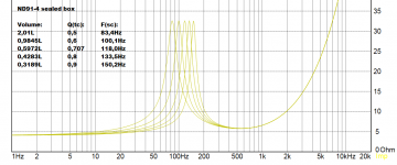
Her some physics that happen. Where system do resonance the impedance increase, and different box size move the frequency where system resonance, as you mention the smaller the box the higher the frequency. Higher impedance less current from amp needed but more voltage swing. Power needed is frequency dependent example 20Hz takes 20W then one octave up 40Hz takes half 10W, 80Hz 5W and so on. Looking at picture 2 you see the biggest box put the bass area 20-200Hz where most power needed to have higher impedance, and therefor less current from amp. The smaller the box the more back waves into the cone that disturb and stresses it and decrease the perceived quality from front of it. Damping material inside box in reality makes box virtual bigger regarding the resonance frequency, therefore try the small one box out heavy stuffed with dampening and see if this works and at same check if sound quality is preserved.
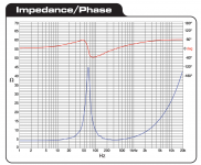
Picture 1 Dayton Audio datasheet resonance free air.
Picture 2 five different sealed box sizes simulated in Winspearkz program.
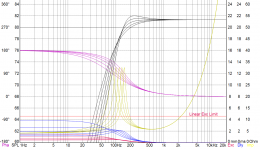
Picture 3 same as second and added specs, 1 watt input to driver.
You mention DSP and clipping if DSP used to boost in LF area amp situation worsen regarding power needed.
Could be tried out if power resistor or a big capasitor highpass filter (CR C=capasitor R=speaker impedance) would improve the amp overload situation, though chance to change perceived quality sound with these added components.
Good point compare locked rotor, if that's reason could be tested or fixed by sealed box with controlled leaking (search web).
Her some physics that happen. Where system do resonance the impedance increase, and different box size move the frequency where system resonance, as you mention the smaller the box the higher the frequency. Higher impedance less current from amp needed but more voltage swing. Power needed is frequency dependent example 20Hz takes 20W then one octave up 40Hz takes half 10W, 80Hz 5W and so on. Looking at picture 2 you see the biggest box put the bass area 20-200Hz where most power needed to have higher impedance, and therefor less current from amp. The smaller the box the more back waves into the cone that disturb and stresses it and decrease the perceived quality from front of it. Damping material inside box in reality makes box virtual bigger regarding the resonance frequency, therefore try the small one box out heavy stuffed with dampening and see if this works and at same check if sound quality is preserved.
Picture 1 Dayton Audio datasheet resonance free air.
Picture 2 five different sealed box sizes simulated in Winspearkz program.
Picture 3 same as second and added specs, 1 watt input to driver.
You mention DSP and clipping if DSP used to boost in LF area amp situation worsen regarding power needed.
Could be tried out if power resistor or a big capasitor highpass filter (CR C=capasitor R=speaker impedance) would improve the amp overload situation, though chance to change perceived quality sound with these added components.
Attachments
Last edited:
In a short and simple statement: When you make the box smaller the efficiency reduces. It shouldn't make that big a difference changing box volume by 20%, but maybe now the amp is run into clipping where with the bigger box it did not.
Clearly there are some things about this topic that I do not understand. The TPA3116D2 data sheet states that the overcurrent protection system trip point is 7.5A. According to BRYTT's chart #2, the minimum impedance for the speaker and enclosure, regardless of frequency, is 4 ohms, which makes sense. Therefore, at 24 volts, the maximum current I should see into a 4 ohm load is 6A, which should not trip the circuit, yet it does. Can any of you explain that?
Clearly there are some things about this topic that I do not understand. The TPA3116D2 data sheet states that the overcurrent protection system trip point is 7.5A. According to BRYTT's chart #2, the minimum impedance for the speaker and enclosure, regardless of frequency, is 4 ohms, which makes sense. Therefore, at 24 volts, the maximum current I should see into a 4 ohm load is 6A, which should not trip the circuit, yet it does. Can any of you explain that?
Can't explain seems weird you can't drive it flawless, though it's known some amp have difficulty at certain difficult loads, but this one seems not to be difficult load with only one driver and no XO.
First suggestion check if voice coil in driver by mistake have been overheated over long time where sometime it melt coil vindings together without burning to open circuit, this sometimes changes DC resistance (Re) to lower impedance which then trip the amp protection, to check the coil use a digital multimeter and measure resistence reading through drivers plugs +/-, Dayton datasheet says 4,1 ohm and your reading should be same or little higher if okay, a guess up to 4,6 ohm.
Second suggest, check mayby another time that PSU for amp have specs that can deliver clean and demanded power. Having an underpowered or dirty PSU sometimes triggers weird behaviors.
Last edited:
Hi again after re-reading post #1, seems that setup sounds good and run flawless in 0,6ltr box, could you confirm this.
It reminds me that if you compensate the lacking bass in the smaller boxes by adding DSP bass, then at higher volume fault could simply be you demand too much in room acoustic bass, that in LF area you hit those high 7,5A currents and the clipping you mention.
It reminds me that if you compensate the lacking bass in the smaller boxes by adding DSP bass, then at higher volume fault could simply be you demand too much in room acoustic bass, that in LF area you hit those high 7,5A currents and the clipping you mention.
Clearly there are some things about this topic that I do not understand. The TPA3116D2 data sheet states that the overcurrent protection system trip point is 7.5A. According to BRYTT's chart #2, the minimum impedance for the speaker and enclosure, regardless of frequency, is 4 ohms, which makes sense. Therefore, at 24 volts, the maximum current I should see into a 4 ohm load is 6A, which should not trip the circuit, yet it does. Can any of you explain that?
See if it trips into a resistive load that draws 6A.
I will post a spectrum of the input signal. As you suspect, most of the energy is in the low frequencies. I am not adding DSP bass, but it is very bassy, nonetheless, which is the nature of the sound. Moreover, that is what I need.
My design goals are:
High SPL
Hi Fidelity (deep resonant bass)
Low weight
Small Footprint
I know, that sounds like pie in the sky, but that is the goal. The ND91-4 drivers work well in achieving my goals. They system sounds good with the 0.6L enclosures. At this point, I am working on the last two goals,
It looks like the current limit is for the whole amp, not for each channel. That suggests that a 4A current on each channel would trigger the current limit. That could happen with 4ohm impedance. I was driving both channels at the same time.
Having a smaller box will increase the air pressure inside the box more.
This will resist the cone moving.
Perhaps reducing any back EMF from the speaker coil ?
You could test this theory with a low ohm resistor in series with the speaker to measure current.
Just wind up a sine wave until you hit max current.
This will resist the cone moving.
Perhaps reducing any back EMF from the speaker coil ?
You could test this theory with a low ohm resistor in series with the speaker to measure current.
Just wind up a sine wave until you hit max current.
- Status
- Not open for further replies.
- Home
- Loudspeakers
- Full Range
- Enclosure changes driver impedance