Okay I was thinking about what exactly is the ultralinear mode and why must it be done by a transformer. For instance I have 2xEL84`s and I noticed in the datasheet that with a 20% tap on the primary of the transformer the maximum power falls only with 1.5W (15.4W) but the distortion falls from 4% to 1.1%. I though, hey that's a nice improvement, but I don't have a transformer with such winding configuration. So I was thinking, the taps work as a negative feedback, but not a 100% like in a triode connection, but with a controlled return coefficient, right? Can`t I emulate the negative feedback from the transformer with some sort of resistor dividers and such. I was thinking something along the line of a triode connection of the output tubes, but with a way to suppress some of the returned signal from the anode to the grid, by perhaps using an RC bypass network or something. Can I have some opinions on whether it`s possible at all, or will I have to just stick to pentode/triode operation.
The problem is that the screen grid draws significant and variable non-linear current, so a passive divider will not give you the same as UL mode tapping. A Mosfet follower for driving the screen grid, from a resistive divider network could work. However, that does not return the screen grid current to the OT, like UL tapping, so still different. One could then put a load resistor on the Mosfet drain with a cap to the plate to return the grid current. B++ for the Mosfet has to be twice the OT B+ though. Essentially just not practical.
One could take the feedbacks back to the screen grids of a driver stage (crossed fed), where the loop gain will be higher, and so the required variation of the screen V is reduced (a more linear insertion point). If one further scales the driver screen V variation proportional to the driver plate V variation (by design of the feedback R divider), then the screens can look like linear resistive loads even. (screens drawing fractional current proportional to the plate current) Stability of the N feedback loop has to be considered with the additional gain.
One could take the feedbacks back to the screen grids of a driver stage (crossed fed), where the loop gain will be higher, and so the required variation of the screen V is reduced (a more linear insertion point). If one further scales the driver screen V variation proportional to the driver plate V variation (by design of the feedback R divider), then the screens can look like linear resistive loads even. (screens drawing fractional current proportional to the plate current) Stability of the N feedback loop has to be considered with the additional gain.
Last edited:
I thought about this several times and finally concluded that the best answer is triode operation with powerdrive. MOSFET source followers or BJT Sziklai pairs can easily drive the grids positive without adding distortion, yielding pentode-like power output with triode distortion and output impedance.
"the best answer is triode operation with powerdrive. "
A practical solution for sure. I would just add some current limiting resistors in the drain or collector path of the power-drives, to limit grid 1 current during input overload conditions.
A practical solution for sure. I would just add some current limiting resistors in the drain or collector path of the power-drives, to limit grid 1 current during input overload conditions.
Can I have some opinions on whether it`s possible at all, or will I have to just stick to pentode/triode operation.
UL is a phenomenon all its own. It's not negative feedback. And the refinement of its application is now over 60 years old with no common, practical, psudo, quasi, affective, acceptable, equal, hacks ever demosnstrated. Plenty of tries with no cigar.
"UL is a phenomenon all its own. It's not negative feedback."
Umm..., NO
Can't agree with that.
One can even calculate the effective triode Mu and Rp of various % UL feedbacks. The problem is the complication of screen grid current distortion interfering with the desired voltage feedback. And that UL mode only restores X% of the screen grid current back to the output OT (so non-ideal itself), which makes for difficult emulation. 100% screen current restoration to the OT (using the complicated Mosfet screen follower above ) should sound BETTER than UL mode, it's just not practical.
Attachments

Last edited:
If it was negative FB the gain would fall in proportion to the UL applied but power output stays high as distortion falls until the optimal UL % is reached vis-a-vis the particular output tube used.
The tube gain DOES fall as more %UL is applied, requiring more drive. (reduced E field at the cathode from the lower screen V, requiring more (+AC wise) grid 1 field to compensate) The power output stays up until the minimum screen V cannot support the plate current needed for maximum output. (the screen V is forced to be too high to begin with, is part of the explanation) One usually uses a different OT primary Z with UL, which complicates the drive comparison.
UL mode IS the wrong place to apply this N feedback though.
UL mode IS the wrong place to apply this N feedback though.
Last edited:
Okay, that was my primary concern too, that the grid current would sag the output voltage too much if it were to be tied directly through a resistor, I was also considering the MOS version or even a triode driving version of some kind, but it seems a bit too complicated for a simple task as to drive a few mA of grid current. I do have 2 transformers with an UL tap for single ended operation, maybe If I use them both it would work. I'm gonna make a few experiments after I find a tube replacement (cuz 1 went haywire) and see what happens. So bottom line, what is UL, a nonlinear negative feedback or something different altogether?
P.S. I was thinking of wiring the EL84 grids as normal with a 3.9k grid resistor and just use a warm biased cathodyne phase splitter to drive the two grids in antiphase. The calculation should be simple enough, I`d just need to figure out the impedance of the grids, make a cathodyne to fit that impedance, and use an AC voltage divider at the input of the cathodyne to tweak the output percentage of the signal. Something like this https://s14.postimg.org/5p6tdazbl/20161019_223834.jpg
P.S. I was thinking of wiring the EL84 grids as normal with a 3.9k grid resistor and just use a warm biased cathodyne phase splitter to drive the two grids in antiphase. The calculation should be simple enough, I`d just need to figure out the impedance of the grids, make a cathodyne to fit that impedance, and use an AC voltage divider at the input of the cathodyne to tweak the output percentage of the signal. Something like this https://s14.postimg.org/5p6tdazbl/20161019_223834.jpg
Last edited:
I was also considering the MOS version or even a triode driving version of some kind, but it seems a bit too complicated for a simple task as to drive a few mA of grid current.
If there's a negative bias supply in the design already, then a low-voltage positive supply is about all that has to be added aside from the MOSFETs and their associated gate stoppers and TVS diodes.
Also consider that grid blocking artifacts are eliminated in this way. There are very few tube amplifier design features that offer such an outsized benefit/cost ratio.
UL is negative feedback, but it is not just negative feedback. The screen grid is both an input (for feedback) and an output (for contributing to the total power), and the screen grid characteristic is neither linear nor identical to the control grid characteristic.
You may be mixing up gain and maximum power output. Gain does fall with UL, but the reduction in distortion means that more input signal can be used to get almost as much power as can be obtained for pentode connection.20t020 said:If it was negative FB the gain would fall in proportion to the UL applied but power output stays high as distortion falls until the optimal UL % is reached vis-a-vis the particular output tube used.
I guess you'd both argue with Hafler on this, too. Would you take is word on it? I can quote him in a direct refute to your characterization of UL. Gain does not fall, sensitivity is maintained, power is maintained and distortion is reduced below triode mode levels, and internal impedance is reduced.
You may be taking some of Williamson's anti-UL sentiment and uninformed statements as gospel. But the gain/power/distortion graphs have been published by Acrosound to show its benefits and unless you have built a set of transformers with varying UL tap points from pure triode through pentode mode you have no data to support your contentions on gain from pentode mode through the increasingly higher % of tap until the optimal UL point is reached. Hafler specifically refers to the maintaining of gain and sensitivity. This is documented in his letter to the editor of Radio Electronics in the Dec. 1953, edition where he responds to a previous article mischaracterizing UL by that author who references Williamson's remarks.
You may be taking some of Williamson's anti-UL sentiment and uninformed statements as gospel. But the gain/power/distortion graphs have been published by Acrosound to show its benefits and unless you have built a set of transformers with varying UL tap points from pure triode through pentode mode you have no data to support your contentions on gain from pentode mode through the increasingly higher % of tap until the optimal UL point is reached. Hafler specifically refers to the maintaining of gain and sensitivity. This is documented in his letter to the editor of Radio Electronics in the Dec. 1953, edition where he responds to a previous article mischaracterizing UL by that author who references Williamson's remarks.
I don't take anyone's word on anything. Feeding the whole anode signal back to g2 definitely reduces gain, as it turns the pentode into a triode. It would be very surprising if returning some fraction of anode voltage leaves gain completely unchanged.
You need to be aware that Hafler's "maintaining gain" may be code for 'does not lose very much gain'.
You need to think about how valves and circuits work, rather than quoting gurus - even well-respected gurus.
Note that to "refute" something is to show/demonstrate that it is false, not merely state (or quote from someone else's statement) that it is false (that would be 'dispute', not 'refute').
Acro's published graphs and Hafler's statements have enough weight to refute your arguement. As far as me needing to "think about how tubes work," ... I've thought quite a bit about how UL works and my theory is that it is like a tuning circuit that improves the function of the screen/anode in parallel with the primary coil. Hafler maintains it is not a FB arrangement. I'd have to go with that and look for the true nature of how UL does what it does. In the end it is what it is, regardless of how you define it or your misanalysis of how it works.
Last edited:
NO! NO! NO!
Just some Hafler audio advertising.
Here is some real data: (1st in pentode, post 352)
http://www.diyaudio.com/forums/tube...eople-dislike-ultralinear-36.html#post4466652
Then real UL in post 359 below it. Notice the curves get closer together. PROOF.
Maybe YOUR UL stays the same. But No one else's does! (here we go again!)
Attachments

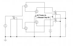
"All Triode UL"
Very interesting! If one were to use approx. 2X higher Mu triodes for the UL feedback paths, one could just use the plate taps instead of the UL taps. Solving the original poster's requirements for a no UL tap OT. (some grid biasing and cathode loads needed at the input for conventional neg. grid tubes)
Very interesting! If one were to use approx. 2X higher Mu triodes for the UL feedback paths, one could just use the plate taps instead of the UL taps. Solving the original poster's requirements for a no UL tap OT. (some grid biasing and cathode loads needed at the input for conventional neg. grid tubes)
Last edited:
My measurements on a single ended amp (Tubelab SSE) in triode, UL and pentode operation both with and without cathode feedback, but no other feedback used in the amp, all point to the total amplifier gain being lowest in triode, significantly higher in UL mode, and higher again in pure pentode mode, but by a lesser amount than the step between triode and UL.
Two Edcor OPT's were used, the $29 smack ones, and the $100 big ones, don't remember the type numbers at this moment, but both were 5K ohms to 8 ohms. Tests were made using 6L6GC, EL34, and KT88. Again the exact numbers are still in a moving box somewhere, but the trend was the same for all test cases.
UL involves two major actions, and several minor interactions. There is an "imperfect" negative feedback mechanism where some of the plates output is fed back into the screen grid.
There is some screen grid current which flows through the OPT contributing a small fraction of the amps total output power. This power output is not likely to be in exact correlation with the power contributed by the plate for all amp operating conditions. This could lead to a lower distortion figure under some conditions, and a higher figure under others. Poor quality OPT's at the frequency extremes is likely to be where the issues lie.
It is possible to emulate the feedback mechanism using a mosfet to drive a portion of the plate signal into the screen grid. Bootstrapping, or a simple two diode or gate can provide a simple drain supply for the mosfet. A pot can be used to achieve a variable UL ratio, but some HF compensation must be applied to counteract the mosfet gate capacitance. A few PF across the gate stopper will do.
I built this, and it works. The power output is similar to true UL, and the distortion and DF is better than pentode mode, but I am not sold on either method for general use. UL with cathode feedback does magic on some OPT's and some music, but for most listening I use pure triode.
Note that all of the above was done on low to mid powered SE amps. I plan to revisit all of this again with 100+ watt push pull amps. Just don't know when.
(some grid biasing and cathode loads needed at the input for conventional neg. grid tubes)
Or you could simply plug PP 6N6G/25N6G into the cct! All selfy biased. But a number of common combos would work. Limited only by one's imagination.🙂
At terrible cost.
John
Or you could simply plug PP 6N6G/25N6G into the cct! All selfy biased. But a number of common combos would work. Limited only by one's imagination.🙂
At terrible cost.
John
Attachments

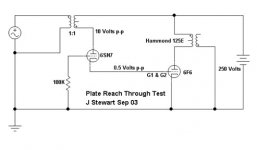
Real Live Test Results
🙂For the curious & others here are the measurement results I got on a SE example of that 'all triode UL' thing. Looks like already 12 years since I messed with this thing!
John L Stewart
🙂For the curious & others here are the measurement results I got on a SE example of that 'all triode UL' thing. Looks like already 12 years since I messed with this thing!
John L Stewart
Attachments
- Status
- Not open for further replies.
- Home
- Amplifiers
- Tubes / Valves
- Emulating Ultra Linear Mode