Sorry if this might be a newbie question:
The background to my question is tube testing with uTracer 3+.
Often when I test allegedly NOS and used tubes, I get low plate current than what stated in the datasheet for specified conditiions. I read in few website that using fixed grid voltage is the wrong way to do emission testing. Here is my question:
Let's assume I test EL84 in the following conditions-
Va=Vs=250V
Vh=6.3V
Vg1=-7.3V
and I get the following results: Ia=30mA, Is=3.5mA
When I increase the grid voltage to -6V, I get Ia=48mA, Is=5.5mA
How one should interpret these results?
I have to say that I'm not in the position to trust the uTracer yet and currently I have no another tester to compare with.
Thanks!
Are you using the built in high voltage supply? I read it works much better with an external supply.
You have no choice then to use the built in high voltage supply, it's inherentAre you using the built in high voltage supply? I read it works much better with an external supply.
in the design !!
You may however use an external filament supply as in some cases the
built in may be off by the pulsed design.
You are in position to trust the uTracer !Sorry if this might be a newbie question:
The background to my question is tube testing with uTracer 3+.
Often when I test allegedly NOS and used tubes, I get low plate current than what stated in the datasheet for specified conditiions. I read in few website that using fixed grid voltage is the wrong way to do emission testing. Here is my question:
Let's assume I test EL84 in the following conditions-
Va=Vs=250V
Vh=6.3V
Vg1=-7.3V
and I get the following results: Ia=30mA, Is=3.5mA
When I increase the grid voltage to -6V, I get Ia=48mA, Is=5.5mA
How one should interpret these results?
I have to say that I'm not in the position to trust the uTracer yet and currently I have no another tester to compare with.
Thanks!
You could increase filament voltage slightly and see if that significantly
changes Ia. An external filament source could be used to calibrate
the ( pulsed) filament source in the uTracer.
Note that tubes differ a lot , +-20% on most values.
I know that the filament internal power supply of the uTracer is not very accurate but I don’t think this is the issue. Assuming the results are reliable, how would you consider the above results?
I know tubes have large tolerances, but often I get much larger deviations than 20% (relative to spec.).. My questions is more regarding the proper procedure for emission testing.
I know tubes have large tolerances, but often I get much larger deviations than 20% (relative to spec.).. My questions is more regarding the proper procedure for emission testing.
What's wrong with the results ? Make some plate cureves and compare with published papers..I know that the filament internal power supply of the uTracer is not very accurate but I don’t think this is the issue. Assuming the results are reliable, how would you consider the above results?
I know tubes have large tolerances, but often I get much larger deviations than 20% (relative to spec.).. My questions is more regarding the proper procedure for emission testing.
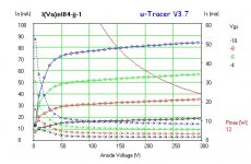
I did.
just like the plate current is lower for the specific grid voltage,the entire curves are lower than the ones you find in the DS (i.e. lower plate values at any point, but the curve shape is OK).
just like the plate current is lower for the specific grid voltage,the entire curves are lower than the ones you find in the DS (i.e. lower plate values at any point, but the curve shape is OK).
Some tubes has lower emissions, some has higher.I did.
just like the plate current is lower for the specific grid voltage,the entire curves are lower than the ones you find in the DS (i.e. lower plate values at any point, but the curve shape is OK).
How many tubes have you tested ? Can you publish an example ?
My experience is similar to yours, using a calibrated AVO Mk4, an L3-3, and static testing.
NOS may be as such because they never met minimum emissions levels so were stuck in a corner and forgotten about. They may also be a bit 'sleepy' and will measure better after 50 or so hours. Wrt Russian 6P14P EL84 equivalents they are excellent but rarely meet EL84 datasheet emissions.
For testing I believe it is function dependent. If the valve goes into a fixed bias circuit then it must be tested accordingly. If it goes into a self bias circuit (like most small signal valves) it should have emissions tested as per datasheet as you have done, and then tested for gM at the specified datasheet Ia by changing the bias to accommodate, since that is how it will be used.
If it is miles out then maybe the bin is the right place for it.
- Home
- Amplifiers
- Tubes / Valves
- Emission test proper procedure and results interpretation