I've been building a few EL84's projects lately and like this tube.
To my understanding, EL84's require only about 20Vp-p for full output.
I've got a Benchmark DAC3L, which can output +28.5dBu or 19Vrms or ~50Vp-p from its balanced XLR output with very low THD.
Could I use it to drive a quad of EL84's directly?
For P-I, perhaps an input transformer such as the Lundahl LL1690 or Sowter 3575
If this is feasible, I would appreciate assistance in designing such a circuit.
Yes. But if you cannot drive it balanced, part of the output stage becomes its own phase splitter and you have half the power.
Easy enuff to try. It would be interesting to see/hear if the Benchmark has sufficient grunt
dave
Easy enuff to try. It would be interesting to see/hear if the Benchmark has sufficient grunt
dave
The Benchmark outputs significantly less in SE so I would have to use balanced.
It was measured over at ASR and it performed as published:
Review and Measurements of Benchmark DAC3 | Audio Science Review (ASR) Forum
It was measured over at ASR and it performed as published:
Review and Measurements of Benchmark DAC3 | Audio Science Review (ASR) Forum
You shouldn't need a phase splitter stage at all not even a transformer-based one (I dont think). This idea is something I've been contemplating in a 6BQ5/PP amp as well... Something with no SE input at all, just an XLR. Since 99.9% of my listening is from my DAC's these days and those all have XLR outputs. Here is something I came across lately not sure if you can forego the driver stage:
View attachment MJ2010_(05)EL84-6BQ5(P)-pp-power-amp_UenoH.pdf
View attachment MJ2010_(05)EL84-6BQ5(P)-pp-power-amp_UenoH.pdf
Don't you need some negative feedback around the output stage to lower the output impedance to have higher damping factors?
I think I prefer higher power so probably go with UL and not triode.
Where would you tie back the gNFB in that case?
Where would you tie back the gNFB in that case?
I think I prefer higher power so probably go with UL and not triode.
Where would you tie back the gNFB in that case?
The schematic I posted above is Pentode or UL. It uses two NFB connections because the whole circuit is balanced end to end.
If going the route of PP EL84 with no driver stage...
Remember that adding NFB will reduce input sensitivity by the amount of NFB.
If you apply 6dB NFB, you'll need to double the signal (+6dB) to the EL84 grids. If the grid bias of the EL84s is -10V, you'll now need that DAC to supply 40Vp-p to the EL84 grids, instead of 20Vp-p.
Perhaps 5W from EL84s in triode with no NFB would be the best compromise if the goal is letting the DAC supply all the signal voltage...
Last edited:
This specific DAC can go up to 19Vrms or 50Vp-p so we can still use it directly.
With the balanced XLR connection, seems like we don't need the phase splitter as the input already supplies the positive and negative polarities.
Can you tie the NFB back directly to the output stage?
With the balanced XLR connection, seems like we don't need the phase splitter as the input already supplies the positive and negative polarities.
Can you tie the NFB back directly to the output stage?
Windcrest77, that schematic is showing +/- 27.5Vrms which is above what the DAC can output. Perhaps needed with the 10.4dB of NFB. Still useful to learn from, thanks
Not PP and not balanced input, so perhaps not applicable or helpful . . . but I built a SE 6BQ5 pentode amp last year that has no preamp tube and uses local NFB.
The amp is a Voice of Music pulled from an old console. The original preamp section was connected via an umbilical and had a normal NFB loop. I wanted to use a variety of preamps instead of the stock one.
Turns out it also works pretty well without any preamp and with only a line level source. So I'd guess that PP would certainly be doable with a stronger input.
This specific DAC can go up to 19Vrms or 50Vp-p so we can still use it directly.
With the balanced XLR connection, seems like we don't need the phase splitter as the input already supplies the positive and negative polarities.
Can you tie the NFB back directly to the output stage?
Plate-grid local NFB?
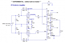
I whipped up an idea in LTspice. It's just an experiment. But I think it gets the idea across, and it does work in simulation (for whatever that's worth...).
Edit to add:
- R3 and R4 are necessary to ground the EL84 grids. Leaving those out lifted them to +51V (not good).
- C2 and C3 obviously don't need to be as large a value as 1uF. I think 0.1uF would do fine. Should be rated 400V minimum.
- R1 and R19, and R2 and R20, are the negative feedback voltage dividers. I was surprised to see how small a value R1 and R2 had to be (10k ohms).
Attachments
Last edited:
Nice, thanks!
I think I will make a proto PCB ... any other parts worth fitting for experimentation?
Do R1 and R2 also serve as grid stoppers or should we add those separately?
I think I will make a proto PCB ... any other parts worth fitting for experimentation?
Do R1 and R2 also serve as grid stoppers or should we add those separately?
Last edited:
- It's really just a thought experiment.
- R1 and R2 are the series resistors for the NFB voltage dividers. They could serve as grid stoppers if they are fitted right to the grid pins on the EL84 sockets.
- Adjust the relative values of R19/R1 and R20/R2 to get the NFB level desired. I adjusted the NFB so that the circuit could reach full power with 12V peak signal input.
I have no idea if this will work well. I wish I had the time to wire something up. Could be done on tagboards easily enough.
I'd suggest 8k and 23%UL instead of 40%, if used together with a-g1 feedback.
With cathode biasing, I'd use Allen Wright's trick to join the caps and ground them through a resistor to reduce IMD.
I'd also increase C2 and C3 voltage rating to 1 kV, as EL84's plates will swing from around 50 to around 630V.
With cathode biasing, I'd use Allen Wright's trick to join the caps and ground them through a resistor to reduce IMD.
I'd also increase C2 and C3 voltage rating to 1 kV, as EL84's plates will swing from around 50 to around 630V.
If using a-g1 feedback would it be better yet to use pentode output stage with regulated g2 supply? More open loop gain that way, so more gain available for NFB, but then more NFB required to attain reasonable damping. Another set of offsetting compromises?
With tubes like EL84 that have good g2 gain, I've found to be simpler and more efficient to have some a-g2 feedback together with a-g1 feedback. This permit to have way more power, not to overload too much the driver, and giving good THD and DF.
IM(limited)E of course.
IM(limited)E of course.
- Home
- Amplifiers
- Tubes / Valves
- EL84 push-pull without driver tube ?