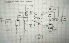
This is the output stage schematic of the Vieta A-225 amplifier (made in Spain in 1968). I've already made some mods, like getting rid of all the pre-amp circuit and replace the capacitors.
The OT's do not have intermediate taps and there is no cathode resistors for biasing the EL84.
¿What is your opinion about this schematic? ¿Would you modify it or just go for a completely new circuit?
Cheers,
The OT's do not have intermediate taps and there is no cathode resistors for biasing the EL84.
¿What is your opinion about this schematic? ¿Would you modify it or just go for a completely new circuit?
Cheers,
Attachments
Yes, I forgot to mention that I've replaced it with a 470 nF Ruby Orange Drop. The bass response has improved a lot. I like the sound.The 47nF seem a bit low.
Those EL84 are being considerably over-run. They are rated for 300V, not 365V.
Grid bias eliminates LF time constants in the cathode circuit (which is good) but means that the output transformer will be subjected to out-of-balance current unless the biasing is constantly monitored.
Using an ECC83 as a concertina is less than ideal because it has quite high output resistance.
I would expect this amplifier to sound good but to be critical of adjustment and to eat output valves.
Yes you're right, Va max is 300V, but I have find the original schematic of this amp, and Va is supposed to be 378V!  I've been playing with a quartet of brand new Tesla for about 40 hours, I hope they're not much damaged.
The PS transformer is rated 300-0-300V, center tapped to ground with a 1,5 Ohm/4W resistor, rectified with two BY225, then a 50uF cap, 150 Ohm resistor in series, another 50uF cap, and there are the 365V.
I've been checking another schematics, and some of them are working at more than 300V. Do they love to run the EL84 in extreme conditions?
http://www.bonavolta.ch/hobby/en/audio/el84.htm
http://www.arrakis.es/~igapop/esquemas.htm
Zip file with schematics
I don't know what to do: modify this schematic reducing the Va and therefore adjusting new bias or go straight to buid a new one. Do some of you have a good one? (OT with no ultralinear taps). I will also buid a new PS with a EZ81 to get rid of that couple of BY225 things.
Thanks for your help
I've been playing with a quartet of brand new Tesla for about 40 hours, I hope they're not much damaged.The PS transformer is rated 300-0-300V, center tapped to ground with a 1,5 Ohm/4W resistor, rectified with two BY225, then a 50uF cap, 150 Ohm resistor in series, another 50uF cap, and there are the 365V.
I've been checking another schematics, and some of them are working at more than 300V. Do they love to run the EL84 in extreme conditions?
http://www.bonavolta.ch/hobby/en/audio/el84.htm
http://www.arrakis.es/~igapop/esquemas.htm
Zip file with schematics
I don't know what to do: modify this schematic reducing the Va and therefore adjusting new bias or go straight to buid a new one. Do some of you have a good one? (OT with no ultralinear taps). I will also buid a new PS with a EZ81 to get rid of that couple of BY225 things.
Thanks for your help
Hi,
It wouldn't surprise me at all if there used to be a EZ81 at one point in time en lieu of the diodes.
Cheers,😉
The PS transformer is rated 300-0-300V, center tapped to ground with a 1,5 Ohm/4W resistor, rectified with two BY225,
It wouldn't surprise me at all if there used to be a EZ81 at one point in time en lieu of the diodes.
Cheers,😉
365V is nothing compared to...
...what Roger Modjesky uses ! Check out the RM10 on the link . 35 watts per channel 700V on the anodes and 350V on the screens . Class A ? Well , errr, no ! He also sells rather expensive graded valves , I wonder why ?
Lock up your Mullard EL84's !
316a
EC8010 said:Those EL84 are being considerably over-run. They are rated for 300V, not 365V.
Grid bias eliminates LF time constants in the cathode circuit (which is good) but means that the output transformer will be subjected to out-of-balance current unless the biasing is constantly monitored.
Using an ECC83 as a concertina is less than ideal because it has quite high output resistance.
I would expect this amplifier to sound good but to be critical of adjustment and to eat output valves.
...what Roger Modjesky uses ! Check out the RM10 on the link . 35 watts per channel 700V on the anodes and 350V on the screens . Class A ? Well , errr, no ! He also sells rather expensive graded valves , I wonder why ?
Lock up your Mullard EL84's !
316a
I like the use of fixed bias better than EC8010 does, but his point on keeping an eye on idle currents is very pertinent. I agree that the 12AX7 does not make a great split-load without something following it with a lower source Z; you might consider reconfiguring the input stage to use a lower Rp triode in that position, or even moving up to a diff amp input. If the screen supply isn't already regulated, do so. The plate supply is less critical in that regard.
And with matched resistors in plate and cathode, you don't need the ac balance adjustment. One less thing to drift or fail.
Assuming the OP transformer is relatively high impedance (like 8Kohm), you might want to check its AC balance side to side and add in some compensation for the higher bandwidth side. This may allow you to reduce the cap in the feedback loop. Also, be careful when increasing coupling caps that you keep the pole well away from the LF rolloff of the transformer to avoid motorboating.
Thank you for your answer. I will experiment with a differential phase splitter as you suggest. Maybe I will try the floating paraphase described in Fig 6.20 of the Morgan Jones book (I've received the book last week, I am just beginning to study it)
Here is the original schematic for this Vieta amplifier, in the case someone is curious about it:
VIETA A-225
Here is the original schematic for this Vieta amplifier, in the case someone is curious about it:
VIETA A-225
Vieta A-225
Hola pingfloid necesito ponerme en contacto contigo, ha caido en mis manos un Vieta A-225 no se si tu tienes uno o solamente estas trabajando con el esquema. Me gustaria tener informacion del Vieta A-225, como potencia por canal, como ajustar el bias si es que se puede, mejoras que le pueda hacer y que altavoces le vendrian bien a este amplificador, lo quiero poner en marcha para oir vinilos. Gracias de antemano y saludos.
Nando.
Hola,
Nando, como somos un forum internacional, las reglas exigen que los miembros escriben en Ingles.
Gracias,😉
Nando, como somos un forum internacional, las reglas exigen que los miembros escriben en Ingles.
Gracias,😉
Vieta A-225
Hi 'pingfloid' I need contact with you, I have a Vieta A-225 and i don't now if you have another or simply you work with the schematic. I need information about Vieta A-225, output power per chanel, bias adjust, enhancements and mods, and which loudspeakers are recomended for this amplifier. I want it to hear LP's. Thanks.
I would like to excuse me with 'Frank' and everybody of the forum for my previous post in spanish.
Nando.
Hola Nando!
I've just move my house, so most of my gear is still packed on boxes and I'm using a "Ciber-cafe" to read my mail.
I'll get in touch with you as soon as I convince my wife that the contents of this boxes deserve a place at the new house... no garbage inside...
I wish no tubes were broken on the move
I've just move my house, so most of my gear is still packed on boxes and I'm using a "Ciber-cafe" to read my mail.
I'll get in touch with you as soon as I convince my wife that the contents of this boxes deserve a place at the new house...
no garbage inside... I wish no tubes were broken on the move
Does anyone have got the electrical Schematics for the VIETA A-215?.
I need to make his tunning.
Thanks in advance!
I need to make his tunning.
Thanks in advance!
- Status
- Not open for further replies.
- Home
- Amplifiers
- Tubes / Valves
- EL84 Push-Pull Vieta A-225 opinion