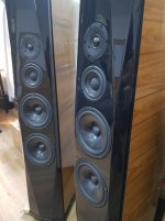
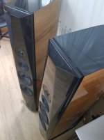
I would like to show one of my another projects I am currently working on. This time it is Ekta Grande upgrade. I had built exactly this pair ~22years ago according to Troels pproject and I used XT25. But soon I wanted to measure and build my own things so I decided to sold those EGs. After the years they came to new owner, living close to where I live, and I was asked to look at them, and suggest an upgrade. I listened to them first and I was a bit dissappointed, overall sound was very big, but also bass and lower midrange lacked structure and definition and trebles did not have spark. I decided to swap tweeter for TW29DN which was physically drop in replacement.
This upgarde started before I learned VituixCADv2 and the new method for measurements in individual drivers elevations. So the first crossovers were based on common mic position measurements. After some trials I started to feel that common mic method especially here is a problem. Using new method brought positive results and clearly showed the problem of common mic position method.
So big THANK YOU goes to Kimmo, and I can say that all my project that were done by VituixCAD v2 actually sound better and are better optimized.
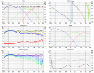
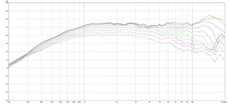
I attached some measurements for individual drivers (horizontals 0-90deg) and also six pack and spinorama graphs.
TW29D is very good sonic match to revelators, and 5deg tilt of the baffle was exactly what was needed to align acoustic centers of the drivers, phase tracking between drivers is exceptional.
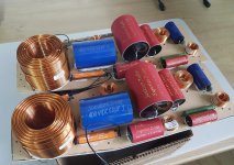
Today I managed to start working on final crossovers, all parts were glued to the boards.
This upgarde started before I learned VituixCADv2 and the new method for measurements in individual drivers elevations. So the first crossovers were based on common mic position measurements. After some trials I started to feel that common mic method especially here is a problem. Using new method brought positive results and clearly showed the problem of common mic position method.
So big THANK YOU goes to Kimmo, and I can say that all my project that were done by VituixCAD v2 actually sound better and are better optimized.
I attached some measurements for individual drivers (horizontals 0-90deg) and also six pack and spinorama graphs.
TW29D is very good sonic match to revelators, and 5deg tilt of the baffle was exactly what was needed to align acoustic centers of the drivers, phase tracking between drivers is exceptional.
Today I managed to start working on final crossovers, all parts were glued to the boards.
Attachments
-
 12M H 0-90.png175.2 KB · Views: 482
 -
 EG Kocour v1 final Spinorama.png29.3 KB · Views: 460
 -
 EG Kocour v1 final.png102.9 KB · Views: 581
 -
 TW29DN H 0-90.png126.5 KB · Views: 463
 -
 20210502_165513.jpg224.3 KB · Views: 486
 -
 20210502_153949.jpg163.7 KB · Views: 447
 -
 20210502_154006.jpg141.2 KB · Views: 319
Hi,
Pipa I notice you conduct power response measurements, questions please:
1. How is power response different from the in-room response? explain.
2. How do you conduct Power response measurements?
Thanks.
Pipa I notice you conduct power response measurements, questions please:
1. How is power response different from the in-room response? explain.
2. How do you conduct Power response measurements?
Thanks.
Xo look very much like Duelund elliptic 3-way (acoustic), which I have found the best in my 3-way projects too. Measurements shown are only horizontal to 90deg, so PI and DI are handicapped - to me they look like being only hor 0-90deg. (Or did you measure in 3D anyway?)
I use dsp-xo when it is very easy to try different xo types and points. Your W/M xo is at 750Hz, which sounds rather high for a floorstander with double woofers... Did you measure also vertical off-axis? 3-400Hz should be doable with that ScanSpeak midrange as well.
Indoor measurements below 500Hz are full of artefacts, reflections...
Attachments

Last edited:
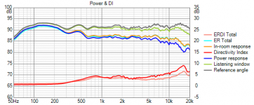
1. In-rooom response uses different calculation, here is a quote from CTA-2034-A:
It shall be comprised of a weighted average of 12 % Listening Window,
44 %, Early Reflections, and 44 % Sound Power. The sound pressure levels shall be converted
to squared pressure values prior to the weighting and summation. After the weightings have
been applied and the squared pressure values summed they shall be converted back to sound
pressure levels.
2. Power response is also calculated. I use Vituix v2 measurement method, so showed graphs contain also vertical behaviour.
I measured 0-90deg only, and dual woofers were measured as one, with the mic right between them => vertical behaviour of the two woofers is not correctly captured here.
This driver combo is not optimal, such a small midrange should be crossed over quite high (hificompass 12M measurement shows steep increase of H4 below 1kHz), but dual woofers should be crossed over below ~400Hz. I do not like pushing such a small midrange low.
I did not measure verticals for individual drivers, I do not have a stand for that.
Crossover design was "free form", I do not use specific targets like Duelund etc.
Hi,
Pipa I notice you conduct power response measurements, questions please:
1. How is power response different from the in-room response? explain.
2. How do you conduct Power response measurements?
Thanks.
Last edited:
Pida, i always enjoy watching your projects.
It does look like a filler driver for little midrange and it looks like Duelund approach given how good phase tracking is, as Juha already mentioned.
It does look like a filler driver for little midrange and it looks like Duelund approach given how good phase tracking is, as Juha already mentioned.
It was just good luck it resulted in Duelund-like acoustic response, though ~800Hz and 3000Hz crossover points were my target points since the beginning and LR2 crossovers too, and it took some time to achieve this as well. I assume drivers have suitable acoustic responses so it intuitively led to Duelund like crossover though I did not design it specifically as Duelund.
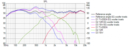
To show the benefit of Vituix V2 method, compared to common mic method, see the attachment.
Graph contains the data measured by v2 method (each driver measured in its elevation), the flat black line is total FR of my final crossover. Total FR with the bump 500-1000Hz is what it looks like with original crossover. It is clear that it is not good. The thing is, when such a dual woofer design is measured from 1m with common mic position the bump is not there in the measurement and crossover modelling.
When I started with upgrade, my intention was too keep woofer crossover as was. With that, I was not able to achieve good sound. I started to anticipate what was the problem, so I just increased value of primary inductor from 1.2 to 1.5 and this brought improvement. This experience (and also experience with Illu3) was the motivation to study v2 method. After v2 measurement and modelling I ended up with 2.7mH coil.
Attachments
Last edited:
To me it looks that with such large CTC spacing of mid&tweet, combined with a rather high mid/tweet x/o, vertical polars most likely will look substantially worse than the nice horizontals now displayed.
How should we weigh the vertical behaviour; how important is it? How would that impact the real power response?
How should we weigh the vertical behaviour; how important is it? How would that impact the real power response?
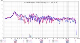
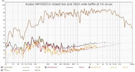
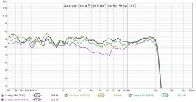
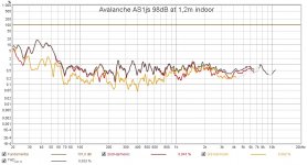
LR2 xo helps drivers near highpass substantially. In my Avalanche project I use Audax HM100, which has Sd almost same as SS 12M
LR2 smooths out vertical response a bit, easy to get smooth room response. Standing up from the chair will naturally make a difference...
LR2 smooths out vertical response a bit, easy to get smooth room response. Standing up from the chair will naturally make a difference...
Attachments
Last edited:
First of all, I see this design, judged strictly by technical measures, as flawed. 1. MT driver spacing is 130mm. Small flange tweeter would be better choice here.
2. Midrange is too small for crossover far below 1kHz, which is required by dual woofers.
As a designer living in real life and working with real drivers, cabinets, and conditions, it is possible to make good sounding loudspeaker despite the flaws.
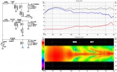
Little bit of background for Vituix v2 and drivers measurement in their individual elevations, for crossover modelling. Each driver was measured in its elevation, 1m mic distance from front baffle. Their relative distances and positions on the baffle are introduced to crossover modelling via XYZRT coordinates of each driver. I use dual channel measurement and by measuring each driver with mic 1m from the front baffle the phase relations are properly measured and maintained.
This method allows to model vertical behaviour quite accurate without doing actual vertical measurements, as Vituix internally mirrors horizontals to verticals and of course manipulates levels and phases to show six pack in virtual mic position. The graphs below show situation in 3000mm. When I change mic distance setting in preferences, I can see that graph little bit changes, and going to 1m it clearly shows that phase tracking of woofer and midrange changes a lot.
I attached vertical map. The sixpack above already contains verticals too => showed power response is already calculated from horizontals and verticals too. The only imperfection or simplification was measuring the dual woofers as one so their vertical behaviour was not properly captured. Woofers share the cabinet volume and I am yet to learn how to deal with that.
=> vertical map around WM crossover is not accurate
My overall design guideline is following:
- in loudspeaker with non-coincident drivers the vertical behavior will never be ideal => I design by horizontals and verticals are just informative
- I address vertical behavior already in "wood-cutting" stage, so I prefer tweeter with small flanges, I also cut the flanges whenever possbile to allow for the closest CtC possible.
- I prefer simpler crossovers unless steeper is required by drivers (dispersion, breakups, resonances,....)
- I prefer crossovers that sum +6dB at crossover
- I keep crossover points as low as possible, having drivers power handling on mind
- listening test is the final judge
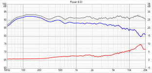
I also attached power response and DI graph to show how it looks when Verticals are switched off (not included in calculation)
2. Midrange is too small for crossover far below 1kHz, which is required by dual woofers.
As a designer living in real life and working with real drivers, cabinets, and conditions, it is possible to make good sounding loudspeaker despite the flaws.
Little bit of background for Vituix v2 and drivers measurement in their individual elevations, for crossover modelling. Each driver was measured in its elevation, 1m mic distance from front baffle. Their relative distances and positions on the baffle are introduced to crossover modelling via XYZRT coordinates of each driver. I use dual channel measurement and by measuring each driver with mic 1m from the front baffle the phase relations are properly measured and maintained.
This method allows to model vertical behaviour quite accurate without doing actual vertical measurements, as Vituix internally mirrors horizontals to verticals and of course manipulates levels and phases to show six pack in virtual mic position. The graphs below show situation in 3000mm. When I change mic distance setting in preferences, I can see that graph little bit changes, and going to 1m it clearly shows that phase tracking of woofer and midrange changes a lot.
I attached vertical map. The sixpack above already contains verticals too => showed power response is already calculated from horizontals and verticals too. The only imperfection or simplification was measuring the dual woofers as one so their vertical behaviour was not properly captured. Woofers share the cabinet volume and I am yet to learn how to deal with that.
=> vertical map around WM crossover is not accurate
My overall design guideline is following:
- in loudspeaker with non-coincident drivers the vertical behavior will never be ideal => I design by horizontals and verticals are just informative
- I address vertical behavior already in "wood-cutting" stage, so I prefer tweeter with small flanges, I also cut the flanges whenever possbile to allow for the closest CtC possible.
- I prefer simpler crossovers unless steeper is required by drivers (dispersion, breakups, resonances,....)
- I prefer crossovers that sum +6dB at crossover
- I keep crossover points as low as possible, having drivers power handling on mind
- listening test is the final judge
I also attached power response and DI graph to show how it looks when Verticals are switched off (not included in calculation)
Attachments
Last edited:
Pida, Thanx for the info.
I am familiar with the Kimmosto/VCad recommended hor. and vert. 5 degree dual channel measurements, albeit that is not so simple in reality as Dave Fred has shown in the VCad thread. The bigger the box the more complex the vertical measurements..
Still I am rather positively surprised about the resuls shown here, given the tweeter works without a real waveguide.
Why do you think a 10 cm cone/soft suspension driver is problematic below 1000Hz in domestic non-studio use?
12M specifically shows higher order distortion rise below 1000Hz, so in that case I wanted to stay with crossover close to that.
10F has actually better distortion below 1000Hz.
4inch drivers like 12MU has no problem with LR2 500Hz crossover. I know that from Illu3 project.
A lot of 3-4inch midranges + the right tweeter can make nice horizontal responses. Usually LR2 is needed, and some measures to mitigate diffractions.
Technically these small drivers are capable of going low with acceptable distortion, and I see projects crossing these drivers ~200-300Hz. I haven't actually tried it, but something tells me not to push them too low otherwise lower midrange could sound thin and loose weight. This is where pure technical view and listening experience or preferences does not match well and I have seen and read different opinions on that.
Last edited:
For 12M more or less yes. I wish Scan Speak used copper shorting rings.....
But generally, if we talk about small midranges crossed over low, let's say below 500Hz, it is just cone area issue.
But generally, if we talk about small midranges crossed over low, let's say below 500Hz, it is just cone area issue.
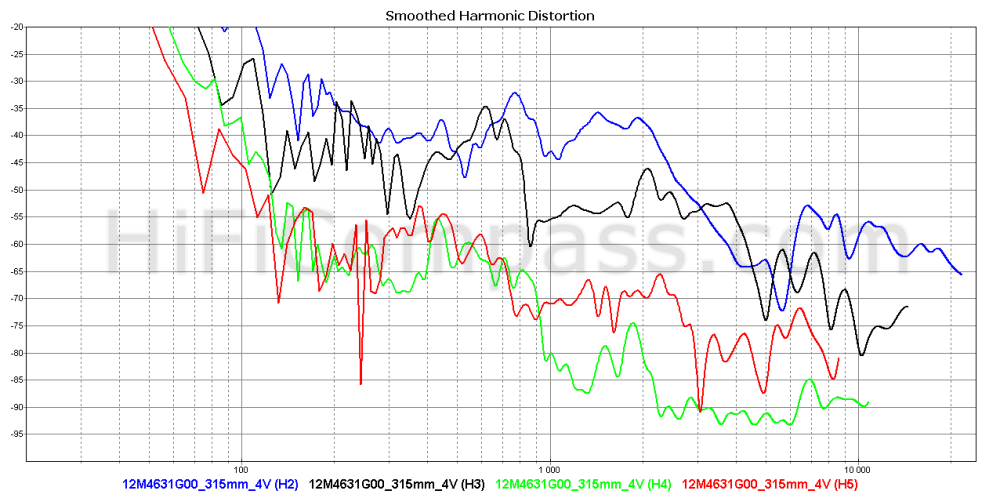
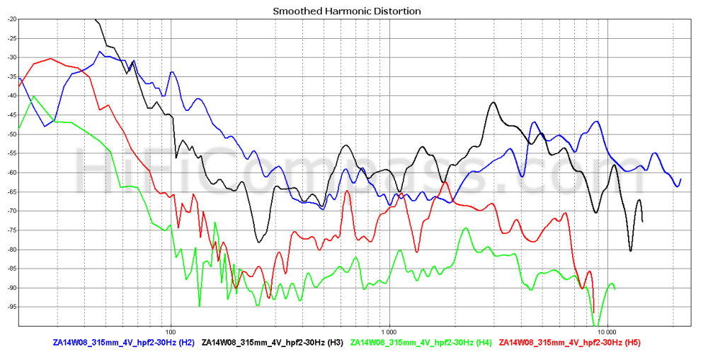
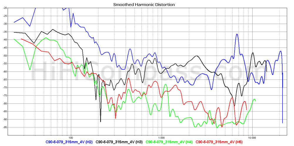
Here distortion measurements from Hificompass.com
SS 12M at 4V Troels says: "The 12M middriver is a darling and an example of excellent performance and delicate industrial design. I don't think it can be done better."
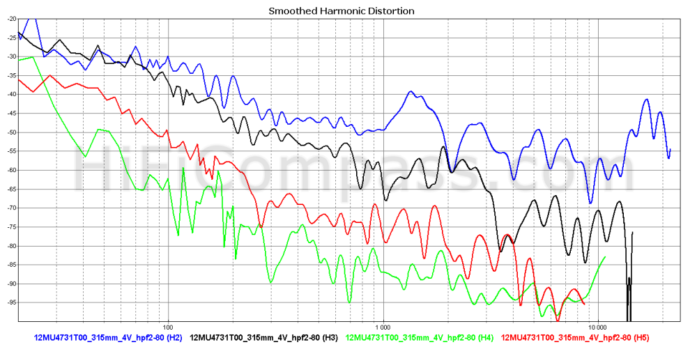
SS 12MU at 4V
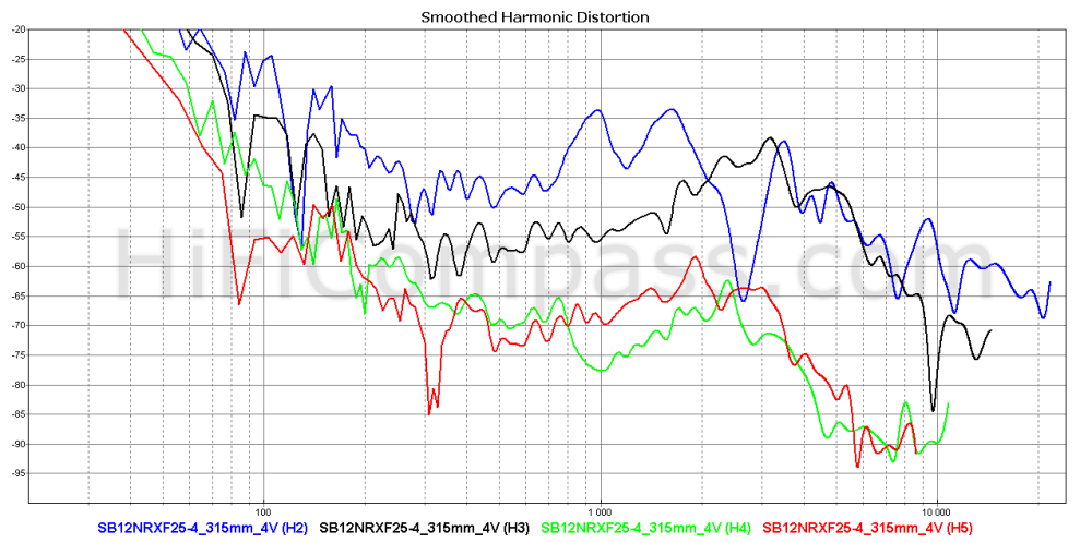
SBA SBA12NRXF25 4V
Zaph ZA14 4V
Accuton C-90 4V
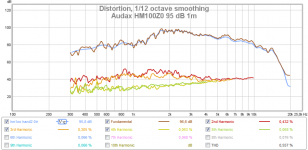
And attached distortion of my 3-way tower with Audax HM100Z0 highpass 350Hz LR2 and not stressed...
SS 12M at 4V Troels says: "The 12M middriver is a darling and an example of excellent performance and delicate industrial design. I don't think it can be done better."
SS 12MU at 4V
SBA SBA12NRXF25 4V
Zaph ZA14 4V
Accuton C-90 4V
And attached distortion of my 3-way tower with Audax HM100Z0 highpass 350Hz LR2 and not stressed...
Attachments
Last edited:
Yes yes I know these graphs very well, still it is just one of several aspects when it comes to how low one can take the midrange crossover.
Yes Pida, I know you know, the post was more to "others" following..
Those distortion graphs show absolute distortion dB at 4V signal. More important is relative distortion%, but it is not available at hificompass. frequency response smoothness is an important factor too...
Spl with 4V signal for previous drivers
Driver 300Hz 1000Hz
SS 12M 93dB 93dB
SS12MU 94 94
SB12 92 92
ZA14 88 89
C90 89 92
- Home
- Loudspeakers
- Multi-Way
- Ekta Grande upgrade