Hi,
I've ordered an EICO 435 to repair as best I can. I'm trying to replace the 2 Can multi capacitors.
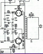
The 2 originals are 40/40/300uf and 20/20/20uf, all at 450V
Would a 500uf be too big to replace the 300uf, or could it be beneficial?
Thanks
I've ordered an EICO 435 to repair as best I can. I'm trying to replace the 2 Can multi capacitors.
The 2 originals are 40/40/300uf and 20/20/20uf, all at 450V
Would a 500uf be too big to replace the 300uf, or could it be beneficial?
Thanks
Attachments
Thanks, I hadn’t noticed that. On the parts list in the manual it says 450v, so I ordered a 330uf 450v
Higher voltage rating is better, especially with actual 430 VDC on the 40uF capacitors in the circuit.
Yes, but it makes for a larger capacitor. I'd use a 63 V.
CE makes great replacement capacitors. www.tubesandmore.com
CE makes great replacement capacitors. www.tubesandmore.com
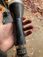
Before switching out the capacitors, I have removed the CRT for general cleaning. It has a metal sleeve between the tube and the bracket holding it in place. There was also an expired gummy material that I cleaned off, which must have been to protect the tube. The metal sleeve was taped to the tube with a yellow tape that had also expired, and I replaced it with 3M electrical tape.
-What would be work well to replace the previously spongy absorption material?
-Is common electrical tape OK to use here or is something heat resistant required?
-When cleaning the metal sleeve, I scratched the paint a bit exposing the metal. Does the black paint serve a purpose?
THANKS.
-What would be work well to replace the previously spongy absorption material?
-Is common electrical tape OK to use here or is something heat resistant required?
-When cleaning the metal sleeve, I scratched the paint a bit exposing the metal. Does the black paint serve a purpose?
THANKS.
Attachments
Don't worry about scratches on the sleeve. It shields the CRT from magnetic fields. You can spray it black again if you want.
The spongy material used to be common foam. The tube only gets hot (more warm) near the base where the heater is. Electrical tape is fine but will probably get gummy over time. You can cut down packing tape, or thicker tape for paper ("Scotch tape").
Once you have it working, you will have to rotate the tube to make your horizontal line .... horizontal. Keep the tube right away from magnets!! Same for the shield you cleaned.
-Chris
I'd like to change the power cord to a grounded 3 wire.
-Would I simply connect Live and neutral as they are, and the ground to chassis? On tube guitar amps I've bypassed a small capacitor when doing this modification. Would the same be done here?
As I've worked on small guitar amplifiers, I am very careful with the high voltages in the power supply capacitors, and always drain them before touching anything. Ive noticed on the schematic that even higher voltages are listed around the CRT.
-What extra precautions should a take in the case of an oscilloscope of this nature? Do the small value high voltage capacitors store voltages long enough to be of concern?
Yes, pretty much. Remove the line cap to chassis. Just be very aware that your probe ground is in fact earth ground now.
You could install a Corcom line filter assembly (or similar from a different manufacturer).
You could install a Corcom line filter assembly (or similar from a different manufacturer).
If I do earth the chassis,
Just be very aware that your probe ground is in fact earth ground now.
is it that I need to be very careful to only connect the probe's ground to grounded points in the equipment I am analyzing?
Yes. This can create ground loops, or big destructive flashes of light and heat (not good). Or it may simply cause a failure in your unit under test. These are the same considerations if the chassis was not grounded because you could bring the chassis of the scope up to whatever circuit potential you clipped to, then zap yourself when you touched the 'scope.
I started when most things were two wire and chassis' could be "hot". I used an oscilloscope older than the one you're rebuilding without a grounded chassis. My meter (VTVM) and everything was floating. We were taught to keep our left hand in our pocket (which I often do even today) - and I got zapped enough times to drill the point home. Circuit failures could place deadly voltages anywhere you least expect it. So, you learned to be careful. We also had home fixers to deal with that would do really stupid things and make equipment dangerous. Most of us survived and became very aware of what we were touching. We still zapped ourselves regularly.
Today most things are pretty safe. Deadly items are old guitar amps, home tube amps and old radios. Not to mention TVs (I hate TVs!!!!). Even an old drill can be deadly.
Thank you. When I opened the oscilloscope, I noticed a loose wire between pin 2 of the CRT and Capacitor C23. Can there be logical reason for that modification being done, or did the wire just become loose accidentally?
When Ive grounded the chassis' on old guitar amps, the capacitor to remove is right by the power switch or the fuse. I don't see anything like that on this circuit. Could you please give me a clue as to how to properly ground this oscilloscope?
When Ive grounded the chassis' on old guitar amps, the capacitor to remove is right by the power switch or the fuse. I don't see anything like that on this circuit. Could you please give me a clue as to how to properly ground this oscilloscope?
Repair it. Check C22 as it may have been defective and was disconnected during troubleshooting.
I unfortunately don't have time to go through grounding for that instrument. I am a working tech and help as I can. Not only that, but on an old product others may have been in there and done something I'm not aware of. I can only ensure your safety if the unit is on my bench in front of me.
If you aren't sure, have a local tech have a look. Some older guys (like me) may look at it for you as a favour.
- Home
- Design & Build
- Equipment & Tools
- EICO 435