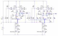
What do you think guys?

Any ideas for improvement?
Suggestions for other FETs or general simplification are encouraged 😀
Any ideas for improvement?
Suggestions for other FETs or general simplification are encouraged 😀
Code:
N-Period=1
Fourier components of V(vout+)
DC component:0.543904

Harmonic	Frequency	 Fourier 	Normalized	 Phase  	Normalized
 Number 	  [Hz]   	Component	 Component	[degree]	Phase [deg]
    1   	1.000e+03	7.166e+01	1.000e+00	 -179.86°	    0.00°
    2   	2.000e+03	2.934e-02	4.094e-04	  118.49°	  298.35°
    3   	3.000e+03	2.897e-02	4.043e-04	   -0.76°	  179.09°
    4   	4.000e+03	5.111e-03	7.133e-05	   -1.85°	  178.01°
    5   	5.000e+03	3.311e-03	4.621e-05	    0.12°	  179.98°
    6   	6.000e+03	2.541e-03	3.546e-05	    0.28°	  180.14°
    7   	7.000e+03	2.223e-03	3.103e-05	    0.11°	  179.97°
    8   	8.000e+03	1.960e-03	2.735e-05	    0.07°	  179.93°
    9   	9.000e+03	1.739e-03	2.427e-05	    0.08°	  179.93°
Total Harmonic Distortion: 0.058469%(0.058897%)


N-Period=1
Fourier components of V(pre+)
DC component:276.361

Harmonic	Frequency	 Fourier 	Normalized	 Phase  	Normalized
 Number 	  [Hz]   	Component	 Component	[degree]	Phase [deg]
    1   	1.000e+03	2.544e+00	1.000e+00	   -0.23°	    0.00°
    2   	2.000e+03	1.041e-03	4.092e-04	 -170.41°	 -170.18°
    3   	3.000e+03	1.148e-04	4.513e-05	  147.59°	  147.82°
    4   	4.000e+03	4.071e-05	1.600e-05	  165.45°	  165.67°
    5   	5.000e+03	6.114e-05	2.404e-05	 -179.09°	 -178.87°
    6   	6.000e+03	5.263e-05	2.069e-05	 -178.94°	 -178.72°
    7   	7.000e+03	4.363e-05	1.715e-05	  179.98°	  180.21°
    8   	8.000e+03	3.823e-05	1.503e-05	  179.92°	  180.15°
    9   	9.000e+03	3.388e-05	1.332e-05	 -179.80°	 -179.57°
Total Harmonic Distortion: 0.041401%(0.041585%)
Attachments
How stable is the DC offset? Also there’s only out+? Push pull differential would have two outputs to the push pull output stage.
I’d also try both 10Khz input and a frequency response using a sweep.
I’d also try both 10Khz input and a frequency response using a sweep.
Last edited:
Just one observation . . .
You have a current sink in the cathodes of the splitter.
You have current sources in the plates of the splitter.
And you have two 220 Ohm resistors between the two cathodes of the splitter.
The following has to be true, or the phase splitter will not bias properly:
Ik = Ip1 + Ip2.
And Ip1 = Ip2.
I believe that is how you set the simulation, Right?
Now . . .
For a real world circuit, and real world parts tolerances . . .
How do you insure that the two plate currents are exactly equal?
How do you insure that the sum of the two plate currents exactly equals the cathode current sink?
That has to hold true, even when temperature of the cathode current sink changes, and the temperature of the two plate current sources changes.
Temperature changes things.
The simple simulation program setup is not going to show that.
Instead, test for a single current sink, or single current source, change of 2.5%:
1. With Ip1 = Ip2
A. Ik + 50uA = Ip1 + Ip2
B. Ik - 50uA = Ip1 + Ip2
2. With Ip1 + 25uA = Ip2
A. Ik = Ip1 + Ip2
B. Ik + 50uA = Ip1 + Ip2
C. Ik - 50uA = Ip1 + Ip2
Now, check what the cathode bias is, and what the two plate voltages are.
Do that for all of the 5 situations: 1.A.; 1.B.; 2.A.; 2.B.; and 2.C..
That will show how good the circuit may, or may not, work.
Generally, it is easy to use current sources in the plates.
Generally, it is easy to use a current sink in the cathodes.
Generally, it is extremely hard to use the combination of both current sources in the plates and current sink in the cathodes in the same circuit.
Just simulate using a 50uA current sink or a 25uA current source as appropriate in parallel across the current sink or current source.
Quite possibly, just doing any 1 of the 5 simulations will prove my point.
Then, do all 5 simulations, and see if you can understand what I am saying.
Please, if you do just 1, or all 5 simulations, for 1.A through 2.C, Then Please let us know the results.
Last edited:
You have a current sink in the cathodes of the splitter.
You have current sources in the plates of the splitter.
Looks to me like gyrators in the plates.
But yes, seems a bit overdone. But I don't know the context and your goals. Are you using the 4 pentodes as finals? Why ECL84? Cost? any special characteristics? Seems like a very complex circuit for such modest tubes.
dgta,
Agreed, a Gyrator at AC/Signal frequencies.
But at DC, in reality, it is a DC current source, Right?
Which gets to my point that the DC currents have to be exactly right with respect to the DC currents of the other two DC currents.
Of course, the exception is that if any triode grid has any quiescent grid leak current, then that makes it even more complex, in order for it to work properly.
What is it intended to drive? It would win a prize for complexity, a nightmare to trouble shoot if any of the many FETs & their associated resistors failed.
Have you run a comparative simulation on a 'Plain Jane' version of the circuit with ordinary R plate loads & single device cathode tails. Need to know if the performance difference justifies the extra parts.
The simulation results will only be as accurate as the tube models used, something to keep in mind. And the output stage will further modify results achieved by even the best designed driver.
My opinions only. Others are sure to differ!🙂
Just relooking at this - the output has a 0.5V dc offset, this could be bias but it can also be imbalance in the LTP configuration - low value plate resistors (and plate load CCS) cause this. The differential signal when summed results in an offset.
Rather than plate ccs you could current mirror, which is what I believe you have at the top hence the joined base of the devices.
Lastly - real world will need some balance trim. If done right you can implement volume control using phase cancellation - noise is then common and cancels out.
Rather than plate ccs you could current mirror, which is what I believe you have at the top hence the joined base of the devices.
Lastly - real world will need some balance trim. If done right you can implement volume control using phase cancellation - noise is then common and cancels out.
Last edited:
Which gets to my point that the DC currents have to be exactly right with respect to the DC currents of the other two DC currents.
Yes. We discussed this at least once before, years ago. You can only specify 2 out of the 3 currents. Someone tried it this way and it "kinda" works only if the 3 current sources are less than perfect, i.e. not very tight. Otherwise it's unstable.
Have you run a comparative simulation on a 'Plain Jane' version of the circuit with ordinary R plate loads
I have, many times with many tubes. With proper design, you get negligible distortion and plenty of gain and swing. In fact it's not necessary to have both stages LTP, if you use a simple VA for the first stage you avoid part of the balance issues and you can DC couple the stages. Just a modern day EICO87.
That's why I asked for the purpose. It's ok to try something out just to try it out, but for practical purposes it's hard to beat the simple proven topologies.
Thanks for comments guys.
My design goals are as follows:
- 2x150Vpp from balanced or single ended source at line level.
- No exotic tubes, preferably one of those old Television tubes of which I have too many just laying around.. (PCL84 in this case)
- Preferably no need for stabilized power supply (decent PSRR)
Some responses to previous posts:
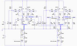
The plate loads are gyrators, plate voltage is set by R24/R29 for the first stage and R8/R7 for the second.
By changing R29, R7, R102 and R105, the working point of the valves can be set. (first two set the voltages, second two the currents)
Yes, complexity..
I'm thinking about making a PCB for this, trying to figure out at this point whether it's worth the effort.
Actually, I have built the circuit without gyrators but was wondering if I could to better...
My design goals are as follows:
- 2x150Vpp from balanced or single ended source at line level.
- No exotic tubes, preferably one of those old Television tubes of which I have too many just laying around.. (PCL84 in this case)
- Preferably no need for stabilized power supply (decent PSRR)
Some responses to previous posts:
The plate loads are gyrators, plate voltage is set by R24/R29 for the first stage and R8/R7 for the second.
By changing R29, R7, R102 and R105, the working point of the valves can be set. (first two set the voltages, second two the currents)
Yes, complexity..
I'm thinking about making a PCB for this, trying to figure out at this point whether it's worth the effort.
Actually, I have built the circuit without gyrators but was wondering if I could to better...

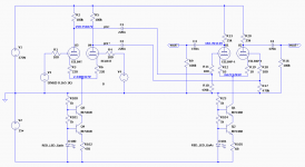
Circuit without gyrators.
Code:
Circuit: * ECL84 resistive load.asc

N-Period=1
Fourier components of V(vout+)
DC component:0.272075

Harmonic	Frequency	 Fourier 	Normalized	 Phase  	Normalized
 Number 	  [Hz]   	Component	 Component	[degree]	Phase [deg]
    1   	1.000e+03	7.357e+01	1.000e+00	  179.90°	    0.00°
    2   	2.000e+03	9.145e-03	1.243e-04	   83.16°	  -96.74°
    3   	3.000e+03	4.466e-01	6.070e-03	  178.65°	   -1.25°
    4   	4.000e+03	5.194e-04	7.060e-06	  -10.88°	 -190.78°
    5   	5.000e+03	9.760e-03	1.326e-04	   -1.65°	 -181.55°
    6   	6.000e+03	3.426e-04	4.656e-06	    0.16°	 -179.75°
    7   	7.000e+03	1.813e-04	2.464e-06	   -0.50°	 -180.41°
    8   	8.000e+03	2.567e-04	3.489e-06	    0.03°	 -179.87°
    9   	9.000e+03	2.276e-04	3.094e-06	    0.11°	 -179.80°
Total Harmonic Distortion: 0.607286%(0.607287%)


N-Period=1
Fourier components of V(pre+)
DC component:259.751

Harmonic	Frequency	 Fourier 	Normalized	 Phase  	Normalized
 Number 	  [Hz]   	Component	 Component	[degree]	Phase [deg]
    1   	1.000e+03	3.075e+00	1.000e+00	   -0.36°	    0.00°
    2   	2.000e+03	1.377e-04	4.476e-05	  -89.97°	  -89.60°
    3   	3.000e+03	2.369e-04	7.704e-05	  -72.57°	  -72.21°
    4   	4.000e+03	8.014e-06	2.606e-06	   -1.98°	   -1.61°
    5   	5.000e+03	7.552e-06	2.456e-06	   87.54°	   87.90°
    6   	6.000e+03	4.201e-07	1.366e-07	 -171.86°	 -171.49°
    7   	7.000e+03	1.634e-07	5.314e-08	 -118.49°	 -118.12°
    8   	8.000e+03	1.118e-07	3.636e-08	  -61.79°	  -61.42°
    9   	9.000e+03	6.482e-08	2.108e-08	 -150.15°	 -149.78°
Total Harmonic Distortion: 0.008917%(0.008922%)
Attachments
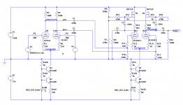
Circuit with gyrators on second stage only.
Code:
Circuit: * ECL84 driver single gyrator.asc

N-Period=1
Fourier components of V(vout+)
DC component:0.456378

Harmonic	Frequency	 Fourier 	Normalized	 Phase  	Normalized
 Number 	  [Hz]   	Component	 Component	[degree]	Phase [deg]
    1   	1.000e+03	8.252e+01	1.000e+00	  179.85°	    0.00°
    2   	2.000e+03	5.690e-02	6.896e-04	  119.91°	  -59.94°
    3   	3.000e+03	3.973e-02	4.815e-04	   -0.02°	 -179.86°
    4   	4.000e+03	3.441e-03	4.170e-05	   -7.13°	 -186.97°
    5   	5.000e+03	2.890e-03	3.502e-05	   -1.24°	 -181.08°
    6   	6.000e+03	7.729e-04	9.367e-06	    1.70°	 -178.15°
    7   	7.000e+03	6.593e-04	7.990e-06	    0.17°	 -179.67°
    8   	8.000e+03	6.899e-04	8.361e-06	   -0.10°	 -179.95°
    9   	9.000e+03	6.097e-04	7.389e-06	    0.09°	 -179.75°
Total Harmonic Distortion: 0.084298%(0.084325%)


N-Period=1
Fourier components of V(pre+)
DC component:248.515

Harmonic	Frequency	 Fourier 	Normalized	 Phase  	Normalized
 Number 	  [Hz]   	Component	 Component	[degree]	Phase [deg]
    1   	1.000e+03	2.819e+00	1.000e+00	   -0.58°	    0.00°
    2   	2.000e+03	6.842e-04	2.427e-04	 -166.00°	 -165.42°
    3   	3.000e+03	1.207e-04	4.280e-05	   59.70°	   60.28°
    4   	4.000e+03	5.428e-05	1.926e-05	    5.49°	    6.07°
    5   	5.000e+03	2.630e-06	9.329e-07	  -88.91°	  -88.33°
    6   	6.000e+03	4.504e-06	1.598e-06	 -174.03°	 -173.45°
    7   	7.000e+03	2.289e-07	8.119e-08	   63.01°	   63.59°
    8   	8.000e+03	4.489e-07	1.592e-07	    4.16°	    4.74°
    9   	9.000e+03	1.039e-07	3.687e-08	  -32.65°	  -32.06°
Total Harmonic Distortion: 0.024721%(0.024721%)
Attachments
You have four µ-follower stage in PP.Why that much gain and why PP with only one input and one output ?
And better take the signal out of the source, not the anode.
Mona
And better take the signal out of the source, not the anode.
Mona
Last edited:
You have four µ-follower stage in PP.Why that much gain and why PP with only one input and one output ?
And better take the signal out of the source, not the anode.
Mona
I' need about 150Vpp from "line level" input. (balanced or not)
The circuit actually has 2 inputs and outputs, I omitted the labels on original schematic 😱
I don't think you can call the circuit a µ-follower in this configuration.
By moving the signal output to the source of the FETs it would become one, but distortion increases.
Attachments
Circuit with gyrators on second stage only.
At what output level are those THD readings taken ?
At what output level are those THD readings taken ?
It says so in the post 🙂 82.5Vrms (8.252e+01)
Circuit with 400V B+ can do almost 300Vpp, with some more distortion of course..
Aha, it's to drive an output stage (with cathode feedback ?)I' need about 150Vpp from "line level" input. (balanced or not)
The circuit actually has 2 inputs and outputs, I omitted the labels on original schematic 😱
But this way you are loading the anodes with the output resistance.Not much benefite anymore of the mosfet at the anodes.I don't think you can call the circuit a µ-follower in this configuration.
By moving the signal output to the source of the FETs it would become one, but distortion increases.
Since you drive the second stage with a symetrical signal the CCS at the cathodes can be replaced with a simple resistor,the sum of the two currents is a constant.
Mona
Last edited:
- Home
- Amplifiers
- Tubes / Valves
- ECL84 as differential push pull driver