Bought this little amp from ebay and it works great amplifying my portable mp3 player.
(circuit diagram inside)
TDA2822M Amplifier Board DIY Parts | eBay
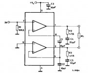
It's a variation of the circuit featured in the datasheet, as it includes C1, C2 and R1.
http://www.circuitdiagram.org/images/TDA2822M-btl-amplifier-circuit.gif
What is the purpose of C1, C2 and R1, filtering?
How can I convert it to amplify my guitar's signal and use headphones as output? (maybe also use an fx pedal between the guitar and amp)
(circuit diagram inside)
TDA2822M Amplifier Board DIY Parts | eBay
It's a variation of the circuit featured in the datasheet, as it includes C1, C2 and R1.
http://www.circuitdiagram.org/images/TDA2822M-btl-amplifier-circuit.gif
What is the purpose of C1, C2 and R1, filtering?
How can I convert it to amplify my guitar's signal and use headphones as output? (maybe also use an fx pedal between the guitar and amp)
Last edited by a moderator:
I must admit I'm puzzled by the circuit. The TDA2822M is a dual amp... no problems there... but the bridged application circuit doesn't make sense tbh at least not in conventional terms. The lower amp has no out of phase input applied to unless the internal architecture of the amp feeds audio via C1. I can't see any other explanation.
So C1 is a coupling cap and feeds audio (that has been shifted internally to be 180 degrees with respect to the input) and C2 will be for stability. The fact C2 is so "large" means the impedance driving C1 must low. R1 defines the input ground and bias point of the amp.
Based on how the circuit looks that would be my best description of it 🙂
Headphones... for stereo use the circuit in the data sheet. For mono I would suggest adding a series resistor and cap and try driving the phones from one half of the bridge, either pin 1 or pin 3 and connecting the phones to ground. Try something like 220uf and say 33ohm. You could drive mono phones across the bridged output but a series resistor for safety would be a good idea. And perhaps a series cap as well to eliminate the risk of DC offsets.
Attachments
I breadboarded the bridge version featured in the datasheet and omitting C1, C2 and R1 produces no significant change while using an 8 ohm load at the output (couple of small speakers in series).
Still, what should I take in account when thinking of using the guitar as a the source?
Still, what should I take in account when thinking of using the guitar as a the source?
If your source is ground referenced (not a floating AC coupled output) then you will get away without R1. Omitting C1 and C2 I am at a loss to explain although I suspect what happens is the load is just driven via half the bridge into an "undefined" output (the lower amp). It would be easy to analyse using a scope... two minutes 🙂
Guitar as a source... you need to know the properties of the output signal from the guitar, specifically impedance and level. I think you would need hi input impedance buffer stage tbh using a FET opamp or discrete JFET source follower..
Guitar as a source... you need to know the properties of the output signal from the guitar, specifically impedance and level. I think you would need hi input impedance buffer stage tbh using a FET opamp or discrete JFET source follower..
If I'm understanding correctly:
If the volume control is 10k and is set at half resistance then it has 5k from the signal source and has 5k to ground so as a part in a filter its resistance is 2.5k ohms.With 100pF to ground its lowpass cutoff frequency is 640kHz to block AM radio stations and higher radio frequencies.
But a magnetic guitar pickup usually has a load of a few megohms so that it has a peak at its resonance of about 5kHz. the 10k volume control will cut its level a lot and cut its high frequencies a lot.
C1 has a source of 2.5k ohms from the volume control set at half resistance and a load of 10k for a total resistance of 12.5k ohms. With the 4.7uf coupling capacitor the highpass cutoff frequency is 2.7Hz so it will pass earthquake frequencies (from a geetar?). Maybe use a 0.33uF (330nF) film capacitor.
Sorry, I missed your post...
Yes, impedance of the source is critical because if its a high impedance piezo type pickup (I know little about the actual pickups used I'm afraid) then loading it with a few k or resistance will kill the voltage. You mention a magnetic pickup... but if its "meg ohm" output impedance then the same applies, any load will shunt the voltage to nothing.
Using a FET buffer or a FET opamp lets you have an amplifier with virtually unlimited impedance, 100's of meg if you wanted.
I wouldn't worry to much at this stage about rf interference... you need to be able to match your pickup correctly first. Might be worth starting a new thread in the "instruments and amps" forum to ask how best to match a pickup to an amp like this 🙂 Give details of the pickup and link the thread to this one.
The amp should work fine 'IF' you put an effects pedal (overdrive , distortion ) between the guitar and amp .... The effects pedal will have a high input impedance and a low output impedance and have enough gain to bring the signal up to line level ......
Minion is correct, as I've tested it just now. All that's left is to take a look at the input capacitors, because there's some unwanted filtering going on. My goal is to understand how these amps work, as most portable hand-held radios (3v stuff) use it and would be a cheap and fun "hack" to change them into pratice amps.
Well , the problem with trying to run a guitar straight into a power amp is firstly the input impedance of a power amp is usually between 10k and 50k and the guitar output impedance is 5k to 50k (and the impedance changes depending on what notes you are playing) and the guitar expects to run into an amplifier that has an impedance 5x to 10x greater than the guitar output impedance ....
What that means is that much of the audio signal coming from your guitar gets lost because of the impedance mismatch , also the guitar signal doesn't have much if any current behind it .....
Putting a pedal between the guitar and the amp acts as a high impedance buffer with gain that can drive your amp .....
😀
- Status
- Not open for further replies.
- Home
- Amplifiers
- Chip Amps
- Ebays TDA2822M BTL to amplify guitar signal