I am new to DIy electronics i ordered a Gain Clone Chip Amp DIY kit on eBay and assembled the components when i tried it today. It was a making a very high pitched sound from the speaker can anyone please suggest what i could have done wrong.
Here is the link to the ebay page.
HIFI DIY kit LM3886TF stereo amplifier board Kit + Amplifier Case+Transformer | eBay
Here is the link to the ebay page.
HIFI DIY kit LM3886TF stereo amplifier board Kit + Amplifier Case+Transformer | eBay
Last edited:
Without much more information, it will be next to impossible. Without schematics, photos, and defining "a very high pitched sound from the speaker" (one speaker or both), I don't think many could venture a sound suggestion.
It is probably oscillating. Do you have access to a scope?
Sigh..
Copper wire 120W oxygen free copper audio cattle.can conncet AC115V or AC230V
Sigh..
Last edited:
Post high resolution pics of your actual build and focus on the connections, you will probably see the issue while taking these pics, but if not you should get help needed here.
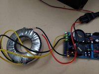
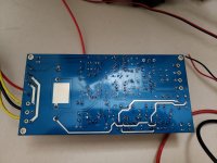
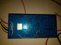
Pics and Schematic Diagram of the build
Hi Every one,
Thanks for your replies here are the pictures and schematic, I am not great at soldering but I did the best I can. The Schematic is not very well most of the components don’t have any values so I improvised by looking at the pictures of the build from eBay listing and checking the PCB layout with sizes of capacitors that fit. In the schematic what does P3 mean? I didn’t connect anything to them as seen in the picture with the red circle. I had connected the main 110V 50Hz (US) line to the transformer without any ground as you can see in the pictures. I see the small LED glow and then with or without the audio input to the board I get that high pitched sound while I connected only one speaker at a time to pins first to Left and then Right, so I don’t blow both speakers if something wasn’t right I have a recording of the sound that for 5 sec. The audio amp chips heat up(LM3886) while this is going on everything seems ok. I don’t have access to a scope can you guys please help me out in getting me to power my first major electronics project.
Regards
Attachments
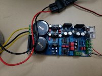
No i had not mounted the LM3886 on the heat sink just wanted to test it before was it a bad move? I powered them for not more than 2 minutes saw them heat up.
"The Schematic is not very well most of the components don’t have any values so I improvised by looking at the pictures of the build from eBay listing and checking the PCB layout with sizes of capacitors that fit. In the schematic what does P3 mean?"
Thats the bit that makes me worry.
Other than the bare wires shoved into a mains socket that is.
P is usually used to denote a trimpot.
Thats the bit that makes me worry.
Other than the bare wires shoved into a mains socket that is.
P is usually used to denote a trimpot.
I think the P3 is just a connecting point for an external power led?
Are the pictures of your finished board? You might want to use more solder in your joints, some look quite bare.
Are the pictures of your finished board? You might want to use more solder in your joints, some look quite bare.
Always use a heatsink.
The input connection, red is ground? The very best solution is coax cable with twisted pair as a second best.
Soldering could be better.
The input connection, red is ground? The very best solution is coax cable with twisted pair as a second best.
Soldering could be better.
Thanks Every one for you replies
I will re solder again and add some more solder and attach the heat sink, the transformer has only 2 leads black and red, as its AC i just put into mains but where do i have a common ground across the circuit ? Should i just solder some thing to the base plate of the metal case ?. Is that the reason for the High Pitch sound I am attaching the mp3 file of the sound i get from speakers here for your reference please help me out every one.
I will re solder again and add some more solder and attach the heat sink, the transformer has only 2 leads black and red, as its AC i just put into mains but where do i have a common ground across the circuit ? Should i just solder some thing to the base plate of the metal case ?. Is that the reason for the High Pitch sound I am attaching the mp3 file of the sound i get from speakers here for your reference please help me out every one.
Attachments
I'll throw this out - my LM3886 from eBay makes weird noises with no input connected. Your photos don't show anything connected to the input, so that's why I am adding this comment. Must be connected to a source, no floating input, or it makes similar sound.
Also - must use a heat sink as others mentioned. I use a 3-prong (grounding IEC plug on your case) and take the ground lug directly to the case. Drill a hole and use a bolt and locking nut to ensure good contact - safety in case you have a short, it will blow the fuse immediately and not cause a shock scenario.
If you have a DMM - check for AC and DC on the outputs. I bet the noise is AC noise.
I was commenting on the amps inputs that should be a coax cable, not the transformer. Also, what are you using as a source? For testing, I use a cd player with a variable output and a chopped in half interconnect.
- Status
- Not open for further replies.
- Home
- Amplifiers
- Chip Amps
- Ebay Gainclone DIY kit makes High Pitch Sounds