As I’m laying out the components inside the chassis I was thinking about earthing. I’m building a stereo unit in one chassis. I’m planning of course to use star earthing but ….. to many points. So I’d like to ask if it’s correct to use,
one star earth at L channel
one star earth at R channel
one star earth at the PSU
and then all these at the chassis with the earth points of the electrolytic caps of PSU that are near the phase splitter and the first stage and mains earth, too.
😕
one star earth at L channel
one star earth at R channel
one star earth at the PSU
and then all these at the chassis with the earth points of the electrolytic caps of PSU that are near the phase splitter and the first stage and mains earth, too.
😕
If you're terminating the ground at several points, it's not star earthing anymore. Star earthing is tough to do and overrated, IMHO. If you're working on a phono preamp it might be worth the extra effort, otherwise it's not a big deal, really.
You may as well just use a ground bus, lots of point to point wired amps use them and work just fine.
🙂
You may as well just use a ground bus, lots of point to point wired amps use them and work just fine.
🙂
Nah, it's just referred to as a multi-point star...
Ground the first stage to its respective input. That's the most sensitive stage and as such you want the least ground loop possible. Like, run the ground end of the cathode or whatever to the ground of the RCA jack (or whatever) input.
You could have 5V ground loop around the output before it sounds as loud as 0.1V fed into the input stage... far more important up front!
Tim
Yup!Nah, it's just referred to as a multi-point star...
@ Sch3mat1c
You mean to ground the first stage on the ground input of the RCA and what about the other earth points?
How to ground them all together on chassis?
My Earthing Method
Ground at the input socket as suggested above. From there run a bussed earth which follows your schematic. ie input valve grid resistor 0V side is the next connection - then input valve cathode connection etc. all the way to the other end which will be the power supply filter cap 0V and depending on the rectifier scheme possibly a power transformer secondary connection as well.
What you are wanting to achieve is NO power supply etc return currents flowing in the SIGNAL ground wires near the sensitive input. With this scheme the largest currents i.e. the power supply filter cap currents, the output valve return currents etc are confined to the end of the earth bus away from the input.
The above sentence is the critical practical objective for ANY Earthing scheme and the bussed earth method is NOT the ONLY way of achieving it. Its just the easiest to follow in your head and debug if there are problems. Think in terms of "prefered paths" (lowest resistance) for the return currents. Whenever the return path for say (for example) the outout valves cathode currents and the input grid resistor earth connection is the same piece of wire you will have problems. If you avoid this sort of situation you won't have any problems.
Actually if you follow the "follows the schematic" earth philosophy you will find that it doesn't really matter which end of the "earth bus" you actually connect to chassis.
I've had good results with eathing at the power supply end or eathing at the signal input end.
If connecting the "earth bus" to chassis at the power supply end I use a local RF bypass cap (10nF Ceramic) from the input socket ground side to chassis. This puts the input cable shield at the same RF potential as the chassis and stops hash getting into the box.
If connecting the "earth bus" to chassis at the input socket(s) I add a 100 Ohm resistor from the power supply end of the bus to chassis just to stop the whole thing floating if the input wire(s)become disconnected.
There should be one and one ONLY direct connection to the chassis for the signal chain for each channel (ignoring the RF cap or the 100R resistor mentioned above (which are "belts and braces" stuff) and this should be physically as far as possible (the other side of the chassis if possible) from the safety earth (mains earth) chassis connection. This because the leakage from mains filters and the mains transformers should return via the safety earth and not flow through the signal chain earth.
Hope this makes sense to you.
Cheers,
Ian
P.S. For your stereo amp with a sigle common supply I suggest common chassis earth point between the input sockets - separate bussed earths (follow the schematic) for each channel and tie them together BUT not to chassis at the powersupply 0V point. Add the optional 100R "safety" resistor to local chassis at the power supply 0V point if you want or just leave it out.
I have an EL84 Ultralinear PP Amp built exactly this way - its never given even a hint of hum.
Hi!
I usually use two-point system of grounding. First point-signal ground Is close to RCA input socket.The signal ground bus begins in this point and comes to an end on connection of a loudspeaker .All earthen points of the amplifier are connected to this bus.
Second point-power ground . The power ground bus begins in this point which is close to power transformer and comes to an end on the last capacitor in the power supply.All earthen points of the PS are connected to this bus.
In my 845 amplifier I use three-point ground system.This amp have two power transformers.
First-signal ground.
Second-power ground for the driver gtage (325VDC)
And third point-power ground for the end stage (1kVDC)
These ways of grounding it is taken from :
I am very sorry for my English.
Attachments
Confused again!
😕
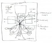
With bus ground, how to connect the ground from reservoir caps, CT of filament windings and main’s earth?
Also, there are reservoir caps near the input stage and phase splitter (you know,for better filtering).Where to connect them?
And if I have a chassis ground btw input RCAs(front of the chassis-near the input tube), how to connect over there the main's earth if the main socket is on the back of the chassis?

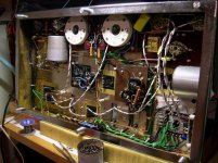
I think something like this in the attached foto is more simple!
I don’t know if it’s better so, heeeelp!

😕
With bus ground, how to connect the ground from reservoir caps, CT of filament windings and main’s earth?
Also, there are reservoir caps near the input stage and phase splitter (you know,for better filtering).Where to connect them?
And if I have a chassis ground btw input RCAs(front of the chassis-near the input tube), how to connect over there the main's earth if the main socket is on the back of the chassis?
I think something like this in the attached foto is more simple!
I don’t know if it’s better so, heeeelp!
Attachments
- Status
- Not open for further replies.
- Home
- Amplifiers
- Tubes / Valves
- earthing