Hello,
Forgive my limited knowledge on how this forum stuff works, been reading alot on here, but unfortunately haven't found anything really relating to my issue.
I'll be giving you the details i have, in hopes that someone here can help point me in a direction.
I bought this t500.1 mono block new from a JL dealer back in 2005ish. Before JL bought them out, or so i was told. Was running it with a kicker L7 12inch, which was quite good, but then ran a 13w6 for about a year. Since its been sitting in a project car. So total use was limited, 2 or 3 years. Then off and on once every year or so.
The unit powers up fine, green power light is on. The yellow and red aren't, only opon start up as it warms up, 3 to 5 seconds....
I started noticing it making a thumping sound when turning off, enough of one to push the sub pretty hard. Over the years it has blown the number 1 and number 4 fuse 1 time. Its only gotten hot enough to thermal once. (120degree day)
Well, i went out to start my car, (drive once or 3 times a year)
The amp powered up like norm, no sound, but thumps hard when turning off...
Checked hu, tried other amps, all work fine. Checked all the obvious stuff, 0 gauge positive and neg, all good. Like i said,dropping in 2 other amps worked great.
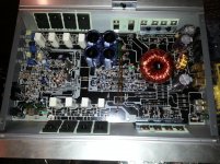
So i took it apart, did a visual, clean as a new one, no corrosion,burnt spots etc, 1 of 4 2200uf 80v caps was bulging, but not ruptured. So i just bought all new and replaced. Bench tested, same results, but i get bumping if i turn the gain to max, and turn up the mp3 player to near max, hit and miss,and destorted as heck. Bench testing before the caps was no different.
I have tested out of circuit, the output transistors, all seem to function properly. The only thing that gets smokin hot is 1 resistor . I would be happy to post pics of anything needed.
At this moment i am stuck, i believe all the mosfets are doing their job,tested every diode i can find etc.... just lost with out some help.
I dont have a scope tho. Just a proper DVOM or " DMM " as i see used regularly here.
I am willing to try anything with some help.
Thank you in advance.
Forgive my limited knowledge on how this forum stuff works, been reading alot on here, but unfortunately haven't found anything really relating to my issue.
I'll be giving you the details i have, in hopes that someone here can help point me in a direction.
I bought this t500.1 mono block new from a JL dealer back in 2005ish. Before JL bought them out, or so i was told. Was running it with a kicker L7 12inch, which was quite good, but then ran a 13w6 for about a year. Since its been sitting in a project car. So total use was limited, 2 or 3 years. Then off and on once every year or so.
The unit powers up fine, green power light is on. The yellow and red aren't, only opon start up as it warms up, 3 to 5 seconds....
I started noticing it making a thumping sound when turning off, enough of one to push the sub pretty hard. Over the years it has blown the number 1 and number 4 fuse 1 time. Its only gotten hot enough to thermal once. (120degree day)
Well, i went out to start my car, (drive once or 3 times a year)
The amp powered up like norm, no sound, but thumps hard when turning off...
Checked hu, tried other amps, all work fine. Checked all the obvious stuff, 0 gauge positive and neg, all good. Like i said,dropping in 2 other amps worked great.
So i took it apart, did a visual, clean as a new one, no corrosion,burnt spots etc, 1 of 4 2200uf 80v caps was bulging, but not ruptured. So i just bought all new and replaced. Bench tested, same results, but i get bumping if i turn the gain to max, and turn up the mp3 player to near max, hit and miss,and destorted as heck. Bench testing before the caps was no different.
I have tested out of circuit, the output transistors, all seem to function properly. The only thing that gets smokin hot is 1 resistor . I would be happy to post pics of anything needed.
At this moment i am stuck, i believe all the mosfets are doing their job,tested every diode i can find etc.... just lost with out some help.
I dont have a scope tho. Just a proper DVOM or " DMM " as i see used regularly here.
I am willing to try anything with some help.
Thank you in advance.
Attachments
This sounds like an open RCA shield ground problem. Do you read 0 ohms between the RCA shield and the negative speaker terminal?
Move the RCA jacks a bit while checking to see if there is an intermittent connection.
Move the RCA jacks a bit while checking to see if there is an intermittent connection.
Hi Perry,
Thanks for the reply.
My readings on the negative speaker to rca is 0.1 ohm.
Sorry i didn't state that previously.
After reading a few hundred of your posts, i tried a few of those little idea's.
Thanks for the reply.
My readings on the negative speaker to rca is 0.1 ohm.
Sorry i didn't state that previously.
After reading a few hundred of your posts, i tried a few of those little idea's.
With no RCAs plugged into the amp, what is the resistance from the RCA to the amp ground. It should not be near 0 ohms.
What is the resistance from the RCA shield on the head unit to the case of the head unit?
What is the resistance from the RCA shield on the head unit to the case of the head unit?
Forgive me for asking, but i have the outputs out of the board, and the board out of the case-heat sink, for testing, should they be reinstalled for this test? And should i reinstall the board in the sink for this?
I ask because the board ground wire goes to the sink, i don't know if that will affect the reading. Like if i had a soft ground or something? Anyway, thank you for your help.
I ask because the board ground wire goes to the sink, i don't know if that will affect the reading. Like if i had a soft ground or something? Anyway, thank you for your help.
Head unit, oh man. Sorry. I'll check that shortly. And get back to you about the head unit.
I am curious tho, the head unit is good, meaning I have been running the same one since new, the entire system was new at the time, and it's been working fine with 2 other amps in the sub circuit.
If the rca's were the problem from the head unit, then bench testing should eliminate all the issues i am experiencing ( in theory) ...
The reading on the amp from ground terminal to rca is 100.0 ohms, that reading is out of the case.
Hello again,
took the readings from hu case to shields, 0.1-0.2ohms.
Thanks for the replies Perry.
took the readings from hu case to shields, 0.1-0.2ohms.
Thanks for the replies Perry.
Does it act the same with a standard head unit as it does with a battery operated mp3 player?
What is the DC voltage on the op-amp power supply pins?
What is the DC voltage on the op-amp power supply pins?
No it doesn't act the same at all. If i use an mp3 setup, it puts out no sound inless i turn the volume up to max, or just before max. I checked the output voltage on the (3.5mm jack to RCA) going to the RCA inputs on the amp, it was peaking at about 3.5 to 4 volts during heavy bass sections of the same "test" song. The preout voltage on my HU is 2volts. So if i turn up the mp3 and max (or close) out the gain, it will pop during bass, but it seems to be distorted, i put a Boston acoustics sub on it, it hit so hard that it blew the voicecoil partially thru the cone. So it does something in those settings, but i get zero function while HU running it.
I'll double check that voltage on the op-amp. Just curious if you have a diagram for this amp. I've been looking with little to no result.
Thank you for your help Perry.
I'll double check that voltage on the op-amp. Just curious if you have a diagram for this amp. I've been looking with little to no result.
Thank you for your help Perry.
I don't have a diagram for this amp.
What is the resistance from the RCA shield to the B+ terminal of the amp?
What is the resistance from the RCA shield to the B+ terminal of the amp?
Hi again Perry,
So i have looked over this thing, and the only thing i can find is confusing as heck. The RCA to b+ is 2.25m ohms, but changes a few hundredths, and seems to settle down around the above mentioned reading.
The datasheet on the op-amp chips (JRC4558D) pinout is simple, but the readings are sorta weird to me, seemingly inconsistent to what i would expect to see, but without proper value specs of what's supposed to be coming and going from this particular area of the amp, so the reading in pinout form are as follows, and if these are useless to you, may you explain what outputs you mean, and where i would expect to locate them on the board from the original picture i posted.
All 3 of these chips read the same way and exact same values.
1: 0.021vdc 8: 14.75vdc
2: 0.012vdc 7: 0.015vdc
3: 0.012vdc 6: 0.015vdc
4: 29.85vdc 5: 0.012vdc
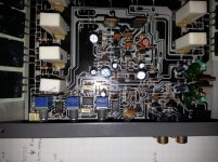
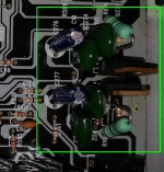
Also, there are 2 light green larger carbon ceramic resistors in the bottom right of the pic that get so hot within 15 to 20 sec of powering up that i can not touch them, and feel heat pouring off them from 8inches away. Doesn't seem to be normal, but i have no clue. The voltages going into those are 55+.... so maybe thats norm....
thank you for your help again.
So i have looked over this thing, and the only thing i can find is confusing as heck. The RCA to b+ is 2.25m ohms, but changes a few hundredths, and seems to settle down around the above mentioned reading.
The datasheet on the op-amp chips (JRC4558D) pinout is simple, but the readings are sorta weird to me, seemingly inconsistent to what i would expect to see, but without proper value specs of what's supposed to be coming and going from this particular area of the amp, so the reading in pinout form are as follows, and if these are useless to you, may you explain what outputs you mean, and where i would expect to locate them on the board from the original picture i posted.
All 3 of these chips read the same way and exact same values.
1: 0.021vdc 8: 14.75vdc
2: 0.012vdc 7: 0.015vdc
3: 0.012vdc 6: 0.015vdc
4: 29.85vdc 5: 0.012vdc
Also, there are 2 light green larger carbon ceramic resistors in the bottom right of the pic that get so hot within 15 to 20 sec of powering up that i can not touch them, and feel heat pouring off them from 8inches away. Doesn't seem to be normal, but i have no clue. The voltages going into those are 55+.... so maybe thats norm....
thank you for your help again.
Attachments
4: 29.85vdc !!! A little high... should be about -14.75. Place the neg lead from your multimeter to the shield of one of the rca jacks, pos lead to pin 4, (-14.75) Then check pin 8, should be about (+14.75). Most amps use a split power supply and will use zener diode's or voltage regulators to get the rail voltage down to aprox. +/- 15 vdc. Try to find the Neg zener diode or regulator... sounds suspect.
Supply Voltage Vcc ±22 V as shown on the data sheet for this op-amp.
Supply Voltage Vcc ±22 V as shown on the data sheet for this op-amp.
The components in the lower right corner (in previous photo) are the regulator components. The resistors are large so that they can dissipate the heat without failing.
The high negative voltage could be due to a defective Zener, bad solder connection or shorted regulator transistor.
The high negative voltage could be due to a defective Zener, bad solder connection or shorted regulator transistor.
Thanks 90scaraudio and Perry, I'll get after that testing, interestingly the other day I was testing it, i just powered it up and saw a white flash, very small but magnesium white bright, and made a very small snapping sound, i looked at where my eye thought i saw it, and it was a zener, at least right in that area. But since they appear to be everywhere on this board, maybe i was mistaken.
Have either of you seen one fail, like in front of your eyes? Do they pop with a flash? I am still gonna test like normal, but wonder if that was a byproduct of the original failure somewhere else in the board. Or if this is a new symptom...
again, thanks for all your knowledge and suggestions.
Have either of you seen one fail, like in front of your eyes? Do they pop with a flash? I am still gonna test like normal, but wonder if that was a byproduct of the original failure somewhere else in the board. Or if this is a new symptom...
again, thanks for all your knowledge and suggestions.
Hey guys, so i took everything apart again and tested every zener outta curcuit, they all test fine, until i put them back in, they test great except for 1, the thing has reverse polarity while in circuit only. This is with all npn's (ifrz46n) out of the board. Logically speaking, something about that curcuit seems off.
Have you ever had one test good out of its intended curcuit, but change in? I have removed it several times to see if its a fluke.... but fails every time.
Have you ever had one test good out of its intended curcuit, but change in? I have removed it several times to see if its a fluke.... but fails every time.
Specifically, which Zener?
What do you mean by 'reverse polarity'?
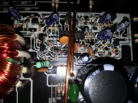
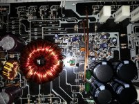
Photo of zener in board (as it is now, not an older photo) and area around it.
What do you mean by 'reverse polarity'?
Photo of zener in board (as it is now, not an older photo) and area around it.
I'm sorry, it has continuity both ways with unlike the others. But only in circuit.
The location is ZD7 just below and left of the chip in the center. I took 2 pics for you. One from a distance, one right above it.
The zener type is c11ph.
The location is ZD7 just below and left of the chip in the center. I took 2 pics for you. One from a distance, one right above it.
The zener type is c11ph.
Attachments
- Status
- Not open for further replies.
- Home
- General Interest
- Car Audio
- Early 2005-6 TMA 500.1 powers up, green light, no sound....