Hello all,
I have tried to build Borbely 60w lateral mosfet amplifier, but it seems that there is something wrong.
Can somebody help me to verify the pcb ?
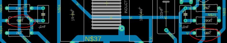
When I connect it to the PSU , 68R resistors (marked on the picture) burns immediately.
All components are genuine and bought from reliable sources.
And to make it more funny, 2pcs of boards will send as gift to guy who help me to make it working, same as this one in attachment or corrected when I get it.
kind regards,
Igor
I have tried to build Borbely 60w lateral mosfet amplifier, but it seems that there is something wrong.
Can somebody help me to verify the pcb ?
When I connect it to the PSU , 68R resistors (marked on the picture) burns immediately.
All components are genuine and bought from reliable sources.
And to make it more funny, 2pcs of boards will send as gift to guy who help me to make it working, same as this one in attachment or corrected when I get it.
kind regards,
Igor
Attachments
Last edited:
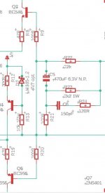
Check your schematic again against borbely's original. right away, i see you have errors in base connections of Q2, Q6 (with R9, R20).
Always a good idea to check continuity for PCBs before stuffing parts and check again after stuffing passives only (before adding semiconductors) to make sure resistances between nodes makes sense.
nothing wrong with borbely's design - it works great; i built it years ago.
Always a good idea to check continuity for PCBs before stuffing parts and check again after stuffing passives only (before adding semiconductors) to make sure resistances between nodes makes sense.
nothing wrong with borbely's design - it works great; i built it years ago.

Hi Igor,
It's not clear from your post--- are you suspecting an error in the PCB layout? I haven't tried to verify artwork, but I imagine an assembly error is more likely to blame.
Foremost suggestion is to power the board from variable bench power supplies so that you can raise supply voltage very gradually and determine where the excessive current is flowing before the 68 Ohm resistors smoke.
My wild guess is damaging current flows through R6,Q8,Q11,Q10,R17.
Make sure P1 is preset to minimum resistance. (I would probably short Q11 collector to emitter initially until all other circuitry was debugged.) But I reiterate, use bench supplies to avoid frustration and heartache.
Good luck!
I just now saw mlloyd1 post.
He's right; I see a faulty connection in the schematic. There's an incorrect connection that shorts feedback (R22,C5) to circuit ground--- connection dot lies right between R13 and R21. This error is in the schematic. I haven't checked if it's present in layout. Even with this error, I'm not sure it would cause smoking 68R.
He's right; I see a faulty connection in the schematic. There's an incorrect connection that shorts feedback (R22,C5) to circuit ground--- connection dot lies right between R13 and R21. This error is in the schematic. I haven't checked if it's present in layout. Even with this error, I'm not sure it would cause smoking 68R.
Hmm, thank you for your effort however I still not sure what is wrong .I just now saw mlloyd1 post.
He's right; I see a faulty connection in the schematic. There's an incorrect connection that shorts feedback (R22,C5) to circuit ground--- connection dot lies right between R13 and R21. This error is in the schematic. I haven't checked if it's present in layout. Even with this error, I'm not sure it would cause smoking 68R.
I have attached my and part from the original sch.
Attachments

BSST is right, there's an error in the original schematic.
This is what it should look like.

This is what it should look like.
yess it looks like the issue. Thank you all for your efforts . I will correct this, and check does it working .
And came back with the results. If it works, prize will go to mlloyd1 and bsst . both will receive pair of my design after correction due to there is no sense to send wrong pcb's .However if someone of you all here need wrong pcb' I will send them after PM (have four on stock).
And came back with the results. If it works, prize will go to mlloyd1 and bsst . both will receive pair of my design after correction due to there is no sense to send wrong pcb's .However if someone of you all here need wrong pcb' I will send them after PM (have four on stock).
Thank you for your kind offer of a reward, but that's not necessary. Seeing your success is my reward. 🙂
Good luck!
Good luck!
Is the Amp fully working with correct bias etc?
what are the Transistors used as Erno' original circuit does not use BC series transistors?
interesting to know
what are the Transistors used as Erno' original circuit does not use BC series transistors?
interesting to know
do not like to describe sound due to it is very subjective thing and in many cases depend on other used components such as used speakers, however by my opinion sound is rich and clear with a lot of details .
- Home
- Amplifiers
- Solid State
- E. Borbely 60w mosfet amplifier