Hi, i have strip and cleaned a original ST70 using original PT and OPT.
See the attached picture of the PCB circuit. All parts are new.
I installed the pcb and used 12AX7 and 12BH7A (12AU7)tubes.
I have +300Vdc to it, fonctions fine.
B+ of the amp is 400Vdc.
But i have trouble with the Dynaco ST70 with feedback loop.
As is with the R7-C11(7,5Kohms and 220pF) feedback of the circuit, amplifier goes into oscillation, high pitch noise.
I did some experiementation on FDB circuit with this same configuration on other tube amps i built before a Scott 6L6 and a 6L6 Heathkit and got excellent results.
Without FDB the ST70 amp is stable as open loop, but low gain, and high distortion THD.
I have tried some different résistors value to find the point were it would remain stable. (changing the value of R7 to have nothing connected, and up to 17,5Kohms to have minimum FDB).
These test i did used the C11 =220pF and did not changed it.
From there i did also tried a use the DynacoST70 classic FBD, directly connected a 1,5Kohms unstead of R7 and add at the screen lower EL34 a 500pF capacitor To the jonction of R9 -R5. On the 12AX7 cathode.
Still high frequency pitch noise once i ramp up B+ voltage to 400Vdc.
SO i kind of trying to swap tubes, but it is a non situation if in the future if you change tubes, it will go oscillation again, not a good idea.
So FBD loop is necessary, but tried to have more feedback, not correct, less feedback by adding series résistors.
All this is is from 16 ohms tap OPT.
Output tubes bias fine at 35mA each.
What do you think, so i try to change C11 for a different value 390pF?? 500pF??
I haven't test the amp with square vawes signal as to haveit stable before i will tweak it for best waveform possible.
Thanks.
See the attached picture of the PCB circuit. All parts are new.
I installed the pcb and used 12AX7 and 12BH7A (12AU7)tubes.
I have +300Vdc to it, fonctions fine.
B+ of the amp is 400Vdc.
But i have trouble with the Dynaco ST70 with feedback loop.
As is with the R7-C11(7,5Kohms and 220pF) feedback of the circuit, amplifier goes into oscillation, high pitch noise.
I did some experiementation on FDB circuit with this same configuration on other tube amps i built before a Scott 6L6 and a 6L6 Heathkit and got excellent results.
Without FDB the ST70 amp is stable as open loop, but low gain, and high distortion THD.
I have tried some different résistors value to find the point were it would remain stable. (changing the value of R7 to have nothing connected, and up to 17,5Kohms to have minimum FDB).
- Add in serie with R7-C11 a 2,2Kohms = no high freq. Pitch noise, but on music transient i get oscillation.
- Or add a 4,7Kohms= same
- Or 10Kohms= no improvements, oscillation on high frequency transients.
These test i did used the C11 =220pF and did not changed it.
From there i did also tried a use the DynacoST70 classic FBD, directly connected a 1,5Kohms unstead of R7 and add at the screen lower EL34 a 500pF capacitor To the jonction of R9 -R5. On the 12AX7 cathode.
Still high frequency pitch noise once i ramp up B+ voltage to 400Vdc.
SO i kind of trying to swap tubes, but it is a non situation if in the future if you change tubes, it will go oscillation again, not a good idea.
So FBD loop is necessary, but tried to have more feedback, not correct, less feedback by adding series résistors.
All this is is from 16 ohms tap OPT.
Output tubes bias fine at 35mA each.
What do you think, so i try to change C11 for a different value 390pF?? 500pF??
I haven't test the amp with square vawes signal as to haveit stable before i will tweak it for best waveform possible.
Thanks.
Attachments
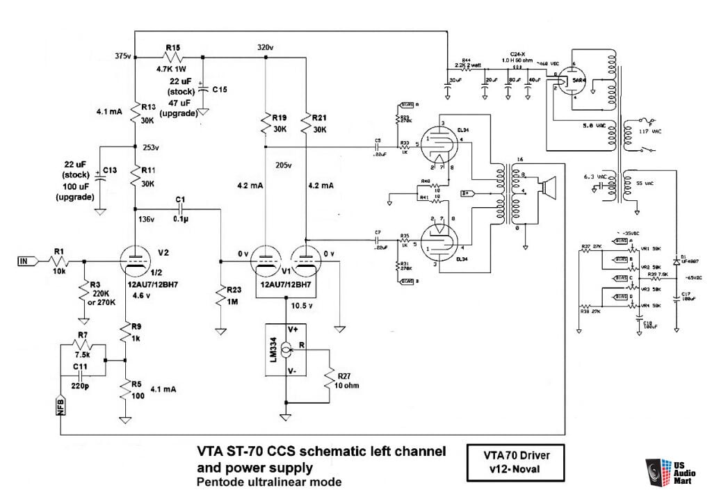
First : the schematics is a rip-off of tubes4hifi . And the first tube cannot be 12ax7 it should be 12au7(ECC82)
Your oscillation comes probably from reversed output transformer leads. Swap the EL34 connections ( v2 - V3 ) (V7 - V6)
Your oscillation comes probably from reversed output transformer leads. Swap the EL34 connections ( v2 - V3 ) (V7 - V6)
Hi , yes i think it is, but it could also be inspired from Poseidon similar CCs circuit using a 12AX7 input tube and 12AU7 as drivers.
I do use this in a Dynaco mk3 monobloc with succes, and no oscillation.
12AU7 as input tube might it, as i understand it it would have to much gain compared to a 12AX7 used as a input stage.
Swapping wiring for output tube would be possible, but lenghts of wirings from OPT is shorter for the closer tube.
Thanks
Attachments

Last edited:
I would be concerned you saying without FB amp is low gain. Without feedback the amp should have a very large amount of gain and not bad distortion. This indicates a fault. With the gain wrong the FB will not behave correctly. Check you have the right tubes in and check the plate and cathode voltages first.
Last edited:
12AU7 as input tube might it, as i understand it it would have to much gain
compared to a 12AX7 used as a input stage.
The 12AU7 has much LESS gain than the 12AX7.
The plate load of the 12AX7 in this circuit is 30k, which is much too low
for proper operation. The 12AX7 grid voltage in this circuit is much too negative.
The circuit appears to have been designed for a 12AU7 input tube.
Last edited:
Agreed the voltages on the schematic for the first stage only become correct for a 12au7. A 12ax7 does not work here, a 12at7 may.
Then switch the driver connections to the EL34 ( instead of transformer leads)Hi , yes i think it is, but it could also be inspired from Poseidon similar CCs circuit using a 12AX7 input tube and 12AU7 as drivers.
I do use this in a Dynaco mk3 monobloc with succes, and no oscillation.
12AU7 as input tube might it, as i understand it it would have to much gain compared to a 12AX7 used as a input stage.
Swapping wiring for output tube would be possible, but lenghts of wirings from OPT is shorter for the closer tube.
Thanks
It SHOULD be a 12AU7 in the first position, as resistors and working point is calculated for that tube. And don't worry about gain, when the amp is running you will have a sensitivity of about a volt for full power.
Dynaco VTA ST70 CCS circuit
Hi,
now using all 12AU7 tubes on circuit.
As per baudoind0 this is the schematic used with the pcb i use.
With the tubes in, got a stable amp on low volume, but giving more volume to test musical power, i get high THD .
I suspect that the R29-31 been 270Kohms are to be 100Kohms.
Did tried to replace with 100Kohms, still high THD but less.(clearly audible)
Test all DC voltage to be right on as indicated in the schematics.
Will use my scope to check voltage swing on C5-7 if THD or clipping is there.
Will also test tube just in case and report back.
BTW what would be the grid no1 resistor value for fixed bias EL34 in this schematics using A470 OPT??
Thanks
Keep resistor values and try good power tubes. This will reduce dist and enable up to 35w power.
What's the voltage at pin 5 of each EL34? I think 270K is OK for EL34 with fixed bias but somebody will correct me if I am wrong.
The most important thing is that the circuit should work as is. Do both channels not work or just one?
The most important thing is that the circuit should work as is. Do both channels not work or just one?
Last edited:
Still high THD on both channels.
Did tests all tubes and all are above minimum on my Hickok KS15750-L1 tube tester.
5AR4 rectifier.
V1-2-3 are 12AU7 and have same very close micromhos triode readings.
EL34 all have -50Vdc on pin5
Each EL34 bias fine around 35mA.
Screen is at +455Vdc or close to +460Vdc.
B+ is 460vdc
Bias is -60Vdc
Each EL34 have a 10 ohms to ground for bias test.
Driver stage is +375Vdc.
Did test driver stage output swing with 1KHz goes unclipped to 110 volts peak to peak, on each C5-C7 coupling caps and have clean waveshape.
Changed the grid resistor untead of 270Kohms, replaced with 100Kohms.
Got this idea from 6550 tubes that are almost a good replacement for EL34, pinout, filament power, etc.
Same high THD on both channel once your ask for more volume.
At low listening it'ok., but to drive a bit , no no
And i'm not pushing it to the max, maybe 5 watts rms?
Amp is stable, no noise, S/N seem excellent, no hum, buzz audible.
Both V1-V3, 12AU7 driver stage plates are 232V-238Vdc so quite similar.
LM334 is measuring 11,7vdc on both 12AU7 cathodes.
V2, 12AU7 input tube is at +128Vdc and cathode at 4,6Vdc.
i'm wandering now about R7 (7.5Kohms), C11 (220pF) feddback circuit.
FDB is tooked from 16 ohms tap. Maybe to test on 8 ohms tap??
DC resistance upon installation of both OPT was OK, C.T. to screen 30 ohms, and 110 ohms on plate connection of each leg.
Main common point star ground to chassis is connect to earth AC cord, did not disconnected it, but could do a test, but it could only bring noise from AC line??
Thanks.
.
Yep 6550 should actually have 50K grid leak but many commercial/guitar designs use 100K. Mr Summer would have something to say about this.
Now -50V on pin 5 of an EL34 @ 460V B+ and screen gives about 5ma rather than 35ma. Is your 10R actually 10R.
Now -50V on pin 5 of an EL34 @ 460V B+ and screen gives about 5ma rather than 35ma. Is your 10R actually 10R.
Last edited:
Yes, my bad 100ohms damnn
Now it's 10 Ohms ok i can use some power with going high THD.
Thanks to baudoin0 to point it out.
Sometimes, it's in your face .....
Now it's 10 Ohms ok i can use some power with going high THD.
Thanks to baudoin0 to point it out.
Sometimes, it's in your face .....

- Home
- Amplifiers
- Tubes / Valves
- Dynaco ST70 with new driver PCB.