Does anyone have a Dynaco SCA-35 amplifier and can provide the dimensions of the two packaged electronic circuit (PEC) modules? These carry part numbers 555002 (for the tone controls) and 555003 (for the input loading). I want to make circuit boards to replace these; the assembly manual provides the schematics but I can't tell much about their physical size from the pictorial diagrams.
Thanks to anyone who can help.
Thanks to anyone who can help.
Without lifting the lid i guess that the PEC's are 40x20mm with all connections at one side. Reducing theirDoes anyone have a Dynaco SCA-35 amplifier and can provide the dimensions of the two packaged electronic circuit (PEC) modules? These carry part numbers 555002 (for the tone controls) and 555003 (for the input loading). I want to make circuit boards to replace these; the assembly manual provides the schematics but I can't tell much about their physical size from the pictorial diagrams.
Thanks to anyone who can help.
size would enhance hum resistance, thus make them as small as possible, but keep them thin.
I've already laid out the boards using surface mount components and plan to take advantage of a PCB assembly service to manufacture them. I just want to make sure I get the dimensions right. My guess is that the input board (555003) is about 25x20mm and that the tone control board (555002) is a little wider than that since it has 7 leads vs. the input board's 5 leads. 40mm for the 555002 looks to be a little wide based on the assembly manual pictorials, but you may be right. Can anyone else verify?
This is very helpful -- thanks!
I plan to use 0603 SMD components so there should be no problem keeping the boards small. A height of 20mm does seem about right for both boards as you indicated. I think the width of the input board (555003) can be about 25mm, and a width of about 40mm for the tone control board (555002) should be enough for its 7 pads and the extra space between pads 1 and 2, and 5 and 6, as shown in the pictorials. This would allow the numbered pads to be spaced about 4-5mm apart on both boards.
Thanks again for your help.
You are not forced to space the connecting wires like the PEC, it would be find running colored wires from one point. Or, maybe even better, a 8 pin connector with matching plug with pre-mounted wires.( the type ofThis is very helpful -- thanks!
I plan to use 0603 SMD components so there should be no problem keeping the boards small. A height of 20mm does seem about right for both boards as you indicated. I think the width of the input board (555003) can be about 25mm, and a width of about 40mm for the tone control board (555002) should be enough for its 7 pads and the extra space between pads 1 and 2, and 5 and 6, as shown in the pictorials. This would allow the numbered pads to be spaced about 4-5mm apart on both boards.
Thanks again for your help.
connectors used in computers), or simply 8 eyelets where user solders connecting wires.
The wide cabling used in the original is prone to pick up hum due to it's size.
Good to know -- thanks. I was planning to use "eyelets" or solder pads for the connections to the board. This would seem to be the least complicated approach and wouldn't compromise performance any more than the original wire leads.
Eliminating the space between pads 1 and 2, and pads 5 and 6, allows the 555002 board width to be comfortably reduced to 32mm. That looks like a good modification -- I'll do that.
Thanks for the advice.
Eliminating the space between pads 1 and 2, and pads 5 and 6, allows the 555002 board width to be comfortably reduced to 32mm. That looks like a good modification -- I'll do that.
Thanks for the advice.

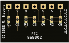
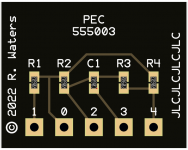
Here is what I have so far. Attached are images of what the assembled circuit boards would look like; these images were produced by JLCPCB's PCB assembly order tool. Although the images are huge the boards themselves are small. The tone control board (555002) measures 20mm tall by 32mm wide, and the input board (555003) measures 20mm tall by 25mm wide. If anyone knows why these board sizes won't work in the SCA-35, please let me know.
I'll put these designs aside for a while and come back to them later with a fresh mind. I've always found that to be a good practice.
Thanks to petertub and PRR for your input.
I'll put these designs aside for a while and come back to them later with a fresh mind. I've always found that to be a good practice.
Thanks to petertub and PRR for your input.
Attachments
I don't know that my input is useful to you. You could pick any spacing. But I had that PEC data and left it here for future researchers.
All input is useful. 🙂 I didn't know that there was any standardization to these kinds of encapsulated parts so I learned something.
Part of my motivation for this project is to simply get some experience designing and fabricating SMD circuit boards. These small PCBs seem like a good place to start.
Part of my motivation for this project is to simply get some experience designing and fabricating SMD circuit boards. These small PCBs seem like a good place to start.
Here is my take on the PEC board.
The board size should just be minimized. It is mounted by flying leads from what I saw in the pictorial so there is nothing constraining the board size or lead spacing. I try to do a single sided layout for this kind of circuit if possible.
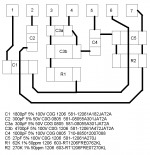
Choose components for most ideal characteristics taking into consideration availability and cost. Resistors would best be thin film 1206 size with tight tempco. Capacitors would be C0G, at least 50V and no smaller than 0805. Parts that need to have a conductor run underneath would best be 1206. The 5000pF capacitor is not a standard value and is made from the parallel combination of two capacitors, 4700pF and 300pF. 300pF is already used elsewhere so is convenient to be part of the parallel pair. My layout is attached. Part numbers are from Mouser.
The board size should just be minimized. It is mounted by flying leads from what I saw in the pictorial so there is nothing constraining the board size or lead spacing. I try to do a single sided layout for this kind of circuit if possible.
Choose components for most ideal characteristics taking into consideration availability and cost. Resistors would best be thin film 1206 size with tight tempco. Capacitors would be C0G, at least 50V and no smaller than 0805. Parts that need to have a conductor run underneath would best be 1206. The 5000pF capacitor is not a standard value and is made from the parallel combination of two capacitors, 4700pF and 300pF. 300pF is already used elsewhere so is convenient to be part of the parallel pair. My layout is attached. Part numbers are from Mouser.
Attachments
Thanks for that, Bill.
As part of this experiment I wanted to try SMD assembly from one of the PCB fab houses. I'm using JLCPCB for now because their assembly process is easy to understand, so I'm constrained to the parts that they have in their library. I actually started with 1206 parts and then 0805, but found that there were a lot more 0603 parts in their library than the larger sizes. If I were going to hand-solder the board, I would definitely go with 1206 SMDs. I'm an old guy and I don't have either the eyesight or the steady hand that would be needed for anything smaller than that.
I do see the advantage in using some 1206 parts, as they are large enough to allow a trace to pass between their pads, something that I wasn't comfortable doing with the smaller parts. I'll take a look at this option because that would allow for a single-sided layout. My current PEC 555003 layout is already single-sided and will work with any size SMD parts.
This is still a work in progress.
Some of the larger capacitance values may be hard to source in 0603, at least for C0G types. X7R and worse dielectrics should not be used in a tone control circuit.
Ed Simon authored an article in Linear Audio that found the thin film 1206 resistors to be the best surface mounted types. Using those will give the best performance without much cost penalty.
It's always best to check what parts are available at distributors especially now with all the shortages and super long lead times.
Bill,
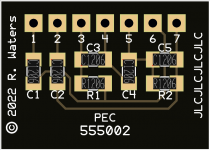
You inspired me. Attached is the single-sided layout I came up with using 1206 SMD parts. It's based on your layout with a few small differences. I suspect that the tolerances of the original parts was probably 10% (5% at best), so the capacitor marked as 5000pF (C3) could have been anything from 4.75 to 5.25nF (at 5%). Since the SMD parts have a 1% tolerance, I think I can get away with 5.1nF for C3 and eliminate the extra parallel capacitor. This simplifies the layout somewhat and allows the board to be shrunk to 28mm wide by 20mm high. That's probably as small as I can make it.
The only issue with this version is that JLCPCB only stocks one of the specified capacitors in the 1206 size, so I would not be able to get them to do the assembly (at least at present). But since this design was more of an educational activity anyway, that's not really a concern at the moment.
Attachments
I finally realized you were interested in sourcing an assembled board, not just a blank board. If the part selection is that limited from the board vendor, for just seven parts, I'd opt to assemble it myself. Then each part can be performance optimized. Your layout looks good.
The 555003 PEC is simple enough that I would probably mount leaded parts on the RCA jacks and not use the PEC.
The 555003 PEC is simple enough that I would probably mount leaded parts on the RCA jacks and not use the PEC.
Yeah, I was looking to experiment with PCB assembly and these small boards can be manufactured at reasonable cost if the parts are in the fabricator's inventory. If they don't have what you need they will buy it, of course, but large minimum quantities apply and that is a game breaker for a hobbyist like me. Based on my parts search experience, the most widely used sizes seem to be 0603 and 0402.
I haven't tried to hand-solder SMD parts yet but I think the 1206 parts are the smallest that I would attempt to assemble manually. Sounds like a new adventure. 🙂
I think you're right about the 555003 input board. Except for the ceramic cartridge, it just applies a resistor to ground from the input jack center pins. And since the ceramic cartridge has been extinct for years there's not much point in supporting it. I would be inclined to just put a resistor to ground there as well so that its input jack isn't left floating.
- Home
- Amplifiers
- Tubes / Valves
- Dynaco SCA-35 PEC Modules