Hi, I need someone to verify if my thought process is correct.
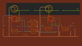
This image is the regular set up for decoupling for supplying power.
IMAGE01
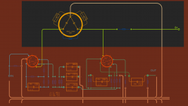
This is what I believe I could do to simplify and reduce cost. By using the 100+100uF JJ cap, it will cost less and take up a little less real-estate.
IMAGE02
So my questions are:
(1) is this how you properly use a dual section cap. (with and without the film caps on the side)
(2) does this create potential ground loop danger? (not as star ground as it could be)
(3) new gained length from caps to anode. Possible bad thing?
Thanks in advance if anyone can give me pointers.
This image is the regular set up for decoupling for supplying power.
IMAGE01
This is what I believe I could do to simplify and reduce cost. By using the 100+100uF JJ cap, it will cost less and take up a little less real-estate.
IMAGE02
So my questions are:
(1) is this how you properly use a dual section cap. (with and without the film caps on the side)
(2) does this create potential ground loop danger? (not as star ground as it could be)
(3) new gained length from caps to anode. Possible bad thing?
Thanks in advance if anyone can give me pointers.
Hi Andrew,
Ya, I am using a remote server to host my images. They were kind of big so I kept them as links instead. If you can't click on them I'll try a different method
Ya, I am using a remote server to host my images. They were kind of big so I kept them as links instead. If you can't click on them I'll try a different method


100uF+100uF @ 500V JJ Can Electrolytic Capacitors:QTY=3 | eBay
If this helps, this is the capacitor in question?
If this helps, this is the capacitor in question?


Difficult to decipher a skeleton board layout. A circuit diagram would be better. A dual cap means sharing the negative connection. Whether this is a problem depends entirely on context.
Thanks N-Brock for the recommendation. Didnt know that uploading to the forum is a safer avenue.
I guess my question doesn't necessarily need a diagram to discuss really.
My question really is 'why would one use a dual capacitor'. From my point of view its to cut down on components and or cost. But I was wondering what it means sonically. (Star ground etc)
I guess my question doesn't necessarily need a diagram to discuss really.
My question really is 'why would one use a dual capacitor'. From my point of view its to cut down on components and or cost. But I was wondering what it means sonically. (Star ground etc)
Dual or triple (or more) capacitors were common in the valve era. Often the negative connection was the can, which was clamped to the chassis. You just connected all grounds to the nearest point on the chassis and let the currents find their own way. This was good enough for radios and amplifiers, as a little hum was regarded as normal back then.
oh interesting! That makes some sense chronologically.
So without a doubt, being that I am interested in reducing hum as much as I can, it is wiser to separate the capacitor grounds to their individual grounds as much as possible.
I had some rough understandings with dual (or more) capacitors, but couldn't find any good literature on the subject.
So without a doubt, being that I am interested in reducing hum as much as I can, it is wiser to separate the capacitor grounds to their individual grounds as much as possible.
I had some rough understandings with dual (or more) capacitors, but couldn't find any good literature on the subject.
There is nothing wrong with separate grounding of the -ve of each of the PSU capacitors.
That is exactly the same as separate the PSU Zero Volts from the Main Audio Ground.
That is exactly the same as separate the PSU Zero Volts from the Main Audio Ground.
Andrew, your thought made me think about ground loops and how two psu's caps independant ripple variations will be so minor it shouldn't really matter at all if they are linked at ground out of the can vs at the star ground.
The bad ground loop scenario would be one with cathodes and other components at the bottom of each stage.
Are my thoughts on ground loops and star grounds somewhat right?
The bad ground loop scenario would be one with cathodes and other components at the bottom of each stage.
Are my thoughts on ground loops and star grounds somewhat right?
- Status
- Not open for further replies.
- Home
- Amplifiers
- Power Supplies
- Dual Section Capacitor