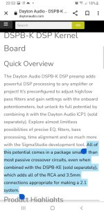
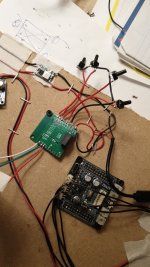
Hi, i'm working on a small portable bleutooth speaker and running against a problem! I wanted to use a dsp board wich you can put an audio signal in and get 3 channels out wich you can add dsp to. I want to make a 3 way configuration and want things as small as possible so i buyed the Dayton dspb-k only, so without the extra Dayton dspb-ke board with 3 channel RCA out. I read on the dayton site that you can use only the dspb-k to minimise volume but you have to solder directly on the board. I don't understand much about the soldering configuration because i'm not that into PCB lay out and stuff.
My question is can someone understand this configuration and help me with adressing the 3 channels out! So subwoofer in/out, left in/out and right in/out! The power is easy, it's just the usb. Thanks!!!
My question is can someone understand this configuration and help me with adressing the 3 channels out! So subwoofer in/out, left in/out and right in/out! The power is easy, it's just the usb. Thanks!!!
Attachments
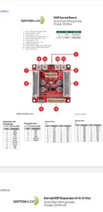
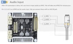
Those are the 4 DAC outputs, DAC0 - DAC3. The stock DSP program appears to be set up for a single channel 3-way. From the PE user manual:
H. Output Section – This section is preconfigured to match the connections for the DSPB-KE as outlined in the above section. DAC0 corresponds to OUTR (tweeter), DAC1 to OUTL (mid), and DAC3 to SUB (woofer).
H. Output Section – This section is preconfigured to match the connections for the DSPB-KE as outlined in the above section. DAC0 corresponds to OUTR (tweeter), DAC1 to OUTL (mid), and DAC3 to SUB (woofer).
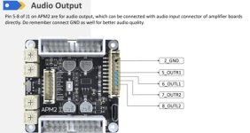
It's been a few years, but this is what I had determined for wiring connections:
DAC0 = OUTR1
DAC1 = OUTL1
DAC2 = OUTR2
DAC3 = OUTL2
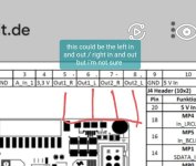
The DAC outputs are also available on the J3 20 pin connector, bur they differ from from J1 connector. This is copied from the FAQ section from the Sure website:
Hi, the output on pins 5 to 8 (J1 connector) is the same on pins 10 to 16 ( J3 connector) ?
Hi, thank you for your interest in our products. Please kindly be noticed that there is a difference between the "OUTL2, OUTR2, OUTL1, OUTR1" of J1 connector and the "OR1, OL1, OR2 OL2" of J3 connector. The pin of J1 is connected with coupling capacitors in series but the pin of J3 is not. Wish this could help you.
DAC0 = OUTR1
DAC1 = OUTL1
DAC2 = OUTR2
DAC3 = OUTL2
The DAC outputs are also available on the J3 20 pin connector, bur they differ from from J1 connector. This is copied from the FAQ section from the Sure website:
Hi, the output on pins 5 to 8 (J1 connector) is the same on pins 10 to 16 ( J3 connector) ?
Hi, thank you for your interest in our products. Please kindly be noticed that there is a difference between the "OUTL2, OUTR2, OUTL1, OUTR1" of J1 connector and the "OR1, OL1, OR2 OL2" of J3 connector. The pin of J1 is connected with coupling capacitors in series but the pin of J3 is not. Wish this could help you.
Thanks for the reply, i gonna use the J1 port because i think that's the "pure" sine signals for the rca outputs but directly soldering on this J1 outputs will allow me to put different connectors on it( gonna solder it directly to the amplifier )
Attachments
I looked up the information but got confused, the dspb-k and ke both have different meanings by the same wiring inputs. I haven't any electric circuit knowledge and get confused easily. I hooked it up how i thought it was in the first place, i didn't get your 4 outputs where there is a 2.1 extention board normally. The sub uses 2 signals which seems logic but somehow i thought it was fused( left and right channel together for sub output mono signal is what i mean) in the board earlier because there is only 3 rca outputs where they could put 4 outputs easily with this boards topology. 3 rca outputs but 4 channel output got me confused easily 😅It's been a few years, but this is what I had determined for wiring connections:
DAC0 = OUTR1
DAC1 = OUTL1
DAC2 = OUTR2
DAC3 = OUTL2
The DAC outputs are also available on the J3 20 pin connector, bur they differ from from J1 connector. This is copied from the FAQ section from the Sure website:
Hi, the output on pins 5 to 8 (J1 connector) is the same on pins 10 to 16 ( J3 connector) ?
Hi, thank you for your interest in our products. Please kindly be noticed that there is a difference between the "OUTL2, OUTR2, OUTL1, OUTR1" of J1 connector and the "OR1, OL1, OR2 OL2" of J3 connector. The pin of J1 is connected with coupling capacitors in series but the pin of J3 is not. Wish this could help you.
Gonna try your way as i found it on the YouTube channel of wondom with pictures and it's like you said. Only additional thing is my 3 amplifiers have to be connected to the ground of the aux input for better audio quality, wondom explains!
I already wired it at the moment the way i thought it has to be in the first place and got a loud background hum, my subwoofer connected the right way but my mid and tweeter both played the full signal. The higher frequencies seems not working but that could be a solder problem.
Attachments
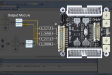
I looked up the video on YouTube and connected the dac 3 and dac 0. One of my 3 amplifiers boards is not working so i have to wait till i get a new one( they are cheap on aliexpress and also directly buyed a better and smaller solder iron ). I connected the ground of the amps to the wondom aux ground and it works now without any noisefloor!!! The only thing is you have to play a bit with the sigma studio as the 3 way mono example from Dayton doesn't work for me. I used the 3way mono example of the kabd-430

- Home
- Amplifiers
- Class D
- DSPb-k soldering instead of using extra DSPb-ke