Hi there guys,
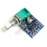
Was wondering how you guys would wire the below amp up? I was thinking of buying terminal blocks like the ones at this mouser link ;
http://www.mouser.com/catalogviewer/default.aspx?page=1876
1. 4 holes for the left/right - output
2. 3 holes for the left/ground/right - input
3. 2 holes for the power
Is this how some of you would do it for a clean wiring layout?
I also have to crimp wires together as based on my little knowledge, I'll be splitting the 5V plug up to run power to this amp & a bluetooth module and an LED light and was just thinking of wiring these together and soldering then shrink tubing together. Do you guys have a better way of doing this with some more intuitive connecting gadgets ? Will also be using a 5v to 5v Murata gadget to eliminate any ground looping issues, thanks to xrk971 for this recommendation.
Attachments
Last edited:
Bring a twisted pair to the Left output.
Another twisted pair to the right output.
Another twisted pair for the +ve & -ve power
Another twisted pair for the Left input. Hold soldering the return.
Another twisted pair for the right input. Now solder the two returns into the middle GND hole. Close couple the two twisted pairs for the inputs and take this 4wire set to the input sockets.
Run pairs of +ve & -ve to each module from the PSU. Don't share any power cables between modules if you can avoid it.
Bring a twisted pair to the Left output.
Another twisted pair to the right output.
Another twisted pair for the +ve & -ve power
Another twisted pair for the Left input. Hold soldering the return.
Another twisted pair for the right input. Now solder the two returns into the middle GND hole. Close couple the two twisted pairs for the inputs and take this 4wire set to the input sockets.
Run pairs of +ve & -ve to each module from the PSU. Don't share any power cables between modules if you can avoid it.
Andrew, thanks a million for taking the time to respond. I'm going to Draw this up to make sure I got it right.
Bring a twisted pair to the Left output.
Another twisted pair to the right output.
Another twisted pair for the +ve & -ve power
Another twisted pair for the Left input. Hold soldering the return.
Another twisted pair for the right input. Now solder the two returns into the middle GND hole. Close couple the two twisted pairs for the inputs and take this 4wire set to the input sockets.
Run pairs of +ve & -ve to each module from the PSU. Don't share any power cables between modules if you can avoid it.
Andrew, what is a Twisted Pair? I dont see where I would need two wires for each +/- audio input / output? Maybe I'm missing something
And what is a return? Really, sorry, all new to this.
Last edited:
![2014-10-09 13_08_51-SPEAKERDIAGRAM [Compatibility Mode] - Microsoft Word.png](/community/data/attachments/406/406551-93e2bb0eb65a1b2d4af1b38fe669a3c8.jpg?hash=k-K7DrZaGy)
It looks good if I understand your notation right. Try to use regular electrical diagram notation. You may need some decoupling caps on the Murata - look at data sheet. The key thing is to not connect the ground between the BT to the ground of the amp.
It looks good if I understand your notation right. Try to use regular electrical diagram notation. You may need some decoupling caps on the Murata - look at data sheet. The key thing is to not connect the ground between the BT to the ground of the amp.
The ground from the Audio you mean? So where would it go? The input on the amp has a slot for it! thanks a million X for your help.
Decoupling Capacitors toooo, lol. Wouldnt a ground loop isolator be cheaper, lol. In the event I need these.
Last edited:
The ground from the Audio you mean? So where would it go? The input on the amp has a slot for it! thanks a million X for your help.
Decoupling Capacitors toooo, lol. Wouldnt a ground loop isolator be cheaper, lol. In the event I need these.
Sorry about the decoupling joke. Just saw the datasheet and it looks like Hieroglyphics to me.
http://power.murata.com/data/power/ncl/kdc_nmv.pdf
What did I get myself into.
Do you have pictures of how you did it?
I don't see the reason for the Murata as long as the audio output of the BT is isolated from the amp via an isolation transformer..
I'd add some ferrite beads to the audio/power input of the amp to stop noise from going back to the BT. Those little amps are noisy rascals, let me tell ya.. (I own several of them)
If you're using a switching type supply, (Puck) I'd use some beads there too. (Input and Output) Don't forget the speaker leads leaving the amp. They become noise broadcasting antennas..
Ok, so as I tried to execute the diagram in real life, I just noticed I have no input ground from the audio cable from the bluetooth to the amp. Where does that Ground come from? Negative from voltage?
Within the amp, the ground (Negative Power) connection and the negative (Shield) of the audio input are at the same potential. There are separate connections on the board for both but they are basically the same. For simplicity reasons, just use the provided connection points..
Isolation in the audio path between the amp and the BT is a must! Don't believe that the shield of the BT and the input of the amp are at the same potential, even if an ohm meter says it is..
An isolation transformer will provide two balanced, separate circuits between the amp and the BT with no physical connection between the two. Use shielded cable between the amp and the BT to the transformer..
Ok, so initially I had a ton of horrible noise washing out the audio. And I noticed that when I placed a cable in the ground slot and touched that cable with my finger it grounded of course, but the noise tremendously dwindled, I decided to see what would make it go away, well I decided to make it touch a pc of the metal from an RCA jack and walla it went away, so I went a step further, I took a wire and jumped it from the Ground to the Left input. And wala no noise. Is this ok to do?
Last edited:
I'll add another funky later, I moved the ground from the left input to the right input and it sounds much better! LOL. I'm so new to this stuff and oblivious.
I tested it for now with the Bluetooth and the Amp on its own power source. Wanted to make sure I wired it up ok for now. I'm going to splice up now and join them and see what happens.
Ok, so I put it all in the same line, and what came back was great news. There's a really really really really really far in the distance wine. I notice it of course, but its super in the distance. Since its so faint, is there another gadget besides an isolator or a murata that could fix that up? Or do I still have to go that route?
NO !Ok, I drew this diagram up. Can you guys review it and let me know if its right. thanks.
The speaker NEEDS TWO wires to work.
Each speaker needs TWO wires to work.
The TWO WIRES get TWISTED together to make a TWISTED PAIR.
- Status
- Not open for further replies.
- Home
- Amplifiers
- Chip Amps
- Drok 5V Audio Amp Wiring