I am modifying an existing design as follows:
Current system:
Rails : +/- 12V
Complemetary pairs: BC337/MJE15029 and BC327/MJE15028, three pairs in total
New system:
Rails: +/-24V
Output transistors: 2SC6144 and 2SA2222 - also maybe KSE44H11 and KSE45H11 (higher voltages, less fT)
Because of the increased voltages I think the BC327/BC337 are very close to their limits (Vceo=45V) so I need to find a suitable driver for the 2SC6144/2SA2222 or the KSE44H11/KSE45H11
I was thinking the BC639/BC640 or the MJE243G/MJE253G.
If you have any other suggestions?
Driver Transistors
I had to search. I really should find a way to copy these useful links into some kind of reference file.
Any ideas?
I had to search. I really should find a way to copy these useful links into some kind of reference file.
Any ideas?
Thanks that 's useful to have showing the complementary pairs. However since my output transistors are TO-220, for their drivers I was looking more into TO-92 or TO-225 packages.
I was looking at the ZTX653/ZTX753 - have these been used in amps at all?
I was looking at the ZTX653/ZTX753 - have these been used in amps at all?
I had to search. I really should find a way to copy these useful links into some kind of reference file.
Any ideas?
Notepad is easiest and quickest. Just paste in the URL and add a title above it that means something to you. To use just swipe the URL and copy and paste directly into browser top line.
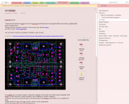
More elegant, use an office type program as I do here. A click on the topic of interest opens the site and page instantly.
You can save anything special (special to you that you want to keep even if the original site disappears) by saving the web page locally on your PC,
http://windows.microsoft.com/en-US/windows-vista/Save-a-webpage-as-a-file
Attachments
Common drivers are MJE350/MJE340.
Common LTP/VAS/current mirror/current source are MPSA42/MPSA92
I have designed loads using these and always had good results.
If you start using fast transistors you start to get problems with oscillation.
Common LTP/VAS/current mirror/current source are MPSA42/MPSA92
I have designed loads using these and always had good results.
If you start using fast transistors you start to get problems with oscillation.
Common drivers are MJE350/MJE340 or MJE15030/MJE15031.
Common LTP/VAS/current mirror/current source are MPSA42/MPSA92
I have designed loads using these and always had good results.
If you start using fast transistors you start to get problems with oscillation.
Common LTP/VAS/current mirror/current source are MPSA42/MPSA92
I have designed loads using these and always had good results.
If you start using fast transistors you start to get problems with oscillation.
2SC6144 and 2SA2222 are also close to their voltage limit. What about BD139/140 as drivers?...New system:
Rails: +/-24V
Output transistors: 2SC6144 and 2SA2222 - also maybe KSE44H11 and KSE45H11 (higher voltages, less fT)...I was thinking the BC639/BC640...
Driver Transistors
I had to search. I really should find a way to copy these useful links into some kind of reference file.
Any ideas?
Hi AndrewT,
For personal reference material I use MS OneNote. It has tabs, pages and sub-pages. Great for capturing screen shots, text, URLs, imbedded documents and graphics etc. It automatically tags information with the cut location's URL. Its easy to edit, format and organised information. Lots of other features, such as a search facility, info is automatically saved, sync to cloud...
It's also free. I can't understand why its not extremely popular?
regards
Attachments
NAP90/ NAIT models used this type of combination for some years with up to 30V rails. ZTX652/752 are the actual parts, in combination with high current TO220s, not unlike those you are considering. The actual types were re-labeled with Naim house codes but being a quasi-complementary design, that is irrelevant. Present day replacements for these would be BD911/912 or similar, in that series.........I was looking at the ZTX653/ZTX753 - have these been used in amps at all?
E-line parts rely on the leads for cooling. Despite their max. current ratings, they will run hot when working hard into low impedance loads with such low gain output types. Trying to cool them via the tiny transistor case won't be enough so ensure there are adequate PCB pads and traces or hard wire them with plenty of space for air movement to improve cooling, if your rail voltages are >20V.
from memory simulation shows overall consymption around 250 mW on each driver. What i am worried about is momentary stresses due to bad bias. i really need a better biasing system...
Driver bias is determined by the output stage component values and the class AB bias current setting. The Naim designs (for example) have been commercially proven using nominal 30V rails with an output rating of 30W/8R. Douglas Self writes in the APADH 5th and 6th ed. that EF driver transistors have almost constant dissipation from idle to full power as they operate largely in class A, so their cooling requirements change little throughout the rated power range.
From what you are suggesting, your design is going to operate well within that spec. so I don't see what your hesitance is based on, unless you haven't seen small drivers used before. If you are dubious then use the BD139/140 drivers and if you say you can't fit T0126 types then it seems likely you wont be able to cool any type of transistor either, due to a cramped layout. Carefully rethink the overall thermal design constraints for uprating this amplifier before getting serious with design details or shopping for components.
From what you are suggesting, your design is going to operate well within that spec. so I don't see what your hesitance is based on, unless you haven't seen small drivers used before. If you are dubious then use the BD139/140 drivers and if you say you can't fit T0126 types then it seems likely you wont be able to cool any type of transistor either, due to a cramped layout. Carefully rethink the overall thermal design constraints for uprating this amplifier before getting serious with design details or shopping for components.
Well I was careless and allowed the current limit to rise to 2A while messing with the bias circuitry and managed to blow something on both rails. From 6 output pairs in total, 2 pairs have blown (either the driver or the power transistor). Oh and I just thought., the current limit on my bench PSU may have not reacted quickly enough to save the transistors. I need to bear that in mind next time!
I was looking at the specs and could not decide between the BC639/640 and the ZTX653/753. The ZTX may have better fT (175 vs 100 MHz).
I was looking at the specs and could not decide between the BC639/640 and the ZTX653/753. The ZTX may have better fT (175 vs 100 MHz).
BC639/40 Ft varies with the manufacturer but the more important limitation is that they can't dissipate significant amounts of heat, despite their 1 amp max. rating, as this won't be a continuous rating as appropriate for an EF driver application. Look at the dissipation limit of 625 mW which even so, assumes you can somehow maintain the transistor at 25 deg. You must allow for a continuous rating based on the package temperature limit or the calculated temperature rise. The E-line package is different and can dissipate significantly more heat but still, this has to be calculated properly.
The point being that you really need to consider carefully what the full datasheets are telling you, because the simple maximum figures seldom tell the whole story. I'm curious what you are referring to with 6 pairs of output transistors - surely you aren't attempting to drive 6 output pairs in parallel?
perhaps you need to clarify what you are doing there, with a schematic.
On simulation the power on the drivers, be that BC639 or ZTX653 is around 45mW, really trivial. What I must be careful for is to avoid exceeding the hard limits of current or voltage. With 50 V across two rails and bad biasing (say disconnected bias transistor, errors on the PCB) the BC327/BC337 drivers would see the whole 50V across them and they are rated at 45V. So I decided to step up and I think now I will try using the ZTX653/753 and see how it goes.
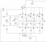
The attached schematic is what I have been using for two months now, and want to upgrade to 24-0-24 rails and faster transistors. The schematic does not show the final transistors choice.
As I said above I think I will go with ZTX653/KSEH4511 and at the bottom ZTX753/KSE44H11. I will test and come back.
Attachments
BTW I forgot to mention this works at a fixed 200KHz so the fact that it works at all is a small miracle. Trying to switch the output transistors off at 200KHz into a 1R load with 8V peak is almost impossible - 8A peak currents. It uses 33R collector resistors and that *just* manages to close the transistors in time to avoid cross conduction.
For this new version I plan to use 62R as a starting point as the currents will be much less.
This condition can be simulated but it is not as severe as the real thing. The simulation may show some cross conduction and that's all. In reality however, the cross conduction generates local heat. So much heat, and so quickly, that immediately you get thermal runaway, or a much increased current if you are lucky to stay short of a full blown runaway, and it happens so fast that the transistor cases are still cold.
I am hoping that the increased rails of this new design, along with faster output transistors, along with much reduced currents (load will now be 6R instead of 1R), percentage wise fewer "fixed losses" - all of those, I hope, will contribute to less cross-conduction issues, and less heat, improved efficiency.
That is why I am looking at faster transistors hence the choice of 2SC6144/2SA2222 as the power output ones. However even these have a Vceo of 50V, which is severely close to the rails. Simulation shows that they would spend between 2.3W and 4W each, which would allow them to reach 120C without blowing up - hopefully. The current system now runs at around 70C, so the new system being more efficient should run less.
I am talking about the output transistors. The drivers are not mounted on the same heatsink and currently reach around 30C-40C tops.
Just to report. I finished a prototype PCB consisting of the ZTX653/753 followed by the 2SC6144/2SA2222.
The bias was set to minimum and I have not got it right, so naturally there was heavy crossover distortion. Unfortunately the 2SC6144/2SA2222 are so quick that the distortion completely obliterated the output, rather than superimpose it self on the output.
It was impossible to make it stable, so I removed all the 2SC6144/2SA2222 and replaced with KSE44H11/KSE45H11. From fT=300MHz to fT=40-50MHz.
After this change, the bias was still wrong, however you could now see on the scope the fundamental (200KHz) and the super-imposed oscillations, I think there must have been over 20 per cycle, therefore around 4MHz. Increasing the bias removes these oscillations, but that did not work at all with the 2SC6144/2SA2222, actually I could not see at all a fundamental, it oscillated so badly it kept tripping the bench PSU.
My power-amp is a current amp (amplifies only current) and has no feedback of any kind. As a result it must be perfect else there will be all sorts of problems (distortions, oscillations) at the output. So I am giving up on the 2SC6144/2SA2222 because they are hard to tame.
A power bandwidth of at least 200kHz is a bit optimistic for conventional audio design technology. Though it has a lot of advantages, a CFP design is always a higher stability risk, whether in audio or more general linear application. In a multiple pair design, this is asking for trouble in spades, particularly by giving it every encouragement to oscillate with high-Ft semis. Ft being the gain-bandwidth product, it may not be the right parameter here, as much as simply the device's frequency limit.
There are no base stoppers, zobel networks or ferrite beads/inductors shown which would be appropriate or at least useful for filtering and stability of a fixed frequency device. There is likely room for much improvement as it stands - unless some details have been omitted for a reason.
Have you considered power Mosfets and class D techniques for this application?
- Status
- Not open for further replies.
- Home
- Amplifiers
- Solid State
- Driver transistors choice