Hi all,
A simple question for discussion. Mainly looking for measurements or some links that explain it technically, but happy to hear user experience too:
Does the driver placement relative to the port in a bass reflex enclosure matter?
To further clarify, I'm wondering if the vent pole of a driver is near the entrance aperture of the port internally, if it matters, or if it needs to be as far away on the port side, or far away opposite the port side (the most indirect pathway for airflow) and if so, why? If it does have a negative impact, is it only on paper or does it manifest audibly? Let's assume the port is sufficiently large to not create noise from excessive air velocities, say, over 18 meters per second or similar for argument. Lastly, does it change with the frequency (ie, does it matter or is it different from say 17hz vs 25hz just as examples)?
Very best,
Last edited:
It shouldn't make a difference if the box is acoustically small.
What would you say is the fuzzy line where it becomes acoustically medium or large? How about in a net internal 8 cubic feet enclosure?
Very best,
My (very uneducated) view: it depends. Some drivers have audible noise from the rear and I wouldn't want this amplified by a port. Many drivers won't have this problem though, and if this isn't an issue, port placement near a driver could be a good thing to help cool the coil.
My understanding of the physics is poor but I believe internal box dimensions will have far more influence on resonances etc. than port placement with respect to the driver, so provided you don't create obvious compression / turbulence near the port entrance/exit you have a good degree of freedom.
My understanding of the physics is poor but I believe internal box dimensions will have far more influence on resonances etc. than port placement with respect to the driver, so provided you don't create obvious compression / turbulence near the port entrance/exit you have a good degree of freedom.

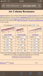
An example is the mass loaded transmission line (MLTL). Here the port is placed along a box mode in the elongated enclosure.where it becomes acoustically medium or large?
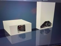
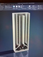
To help with the idea, here's an example, I was modeling an 8 cubic foot enclosure with some scrap ply. This is not the final sub enclosure, this is just a physical model to play with ideas and test things outside of software before I commit to a couple of these in nicer birch. But before I move forward, I was wondering if the driver placement near the port entrance like this is a problem, or if it just doesn't matter. Currently going to put a Dayton MX15-22 driver in here. That port is tuned at 19hz for a slot port and braced. The internal enclosure lacks bracing in these photos, again, this is a physical model just to test various things before committing to the final build which will have more bracing and be made of birch. This is a 50" x 20" x 20" (give or take a tiny bit) and the driver is centered. The port is on the back of the enclosure and will vent out of the top rear (was simplifying the port to avoid folding it a bunch since its a larger 3" x 18.75" port. The final will have two baffles where the driver is and a stud cage around it and bracing throughout the rest. For this purpose though, just trying to figure out if the driver can be centered, or if it needs to be more to one (top or bottom) of this enclosure relative to that port opening.


Very best,
Very best,
Externally, 50" x 20" x 20" and the driver was centered in this model, with this scrap OSB ply, not meant to be a final working system, but a test fitting and seeing how the enclosure would ultimately be after modeling and calcing but I've never built a larger one like this (for me), I've done smaller 3~5 cubic foot stuff, but 8 cubic foot is pretty big for me. Looking to build 4 of them for the room. But before moving forward, just want to make sure I'm not making a crucial error in placement relative to the port.
Makes sense to think of it in harmonic orders based on dimensions, thanks, going to play around with that.
Very best,
Makes sense to think of it in harmonic orders based on dimensions, thanks, going to play around with that.
Very best,
Your longer dimension is going to give the first cancellation at 135Hz with the driver in the middle. As this is a sub and it's tuned at 19Hz, it should be OK. The port won't be doing anything worthwhile at 135Hz. If there is a reduction in cone output it can either help you in crossing, or you can reduce it with stuffing. You'll also have wall vibrations to consider.
Your longer dimension is going to give the first cancellation at 135Hz with the driver in the middle. As this is a sub and it's tuned at 19Hz, it should be OK. The port won't be doing anything worthwhile at 135Hz. If there is a reduction in cone output it can either help you in crossing, or you can reduce it with stuffing. You'll also have wall vibrations to consider.
Thanks; if it's not going to be an issue for the port tuning value or kill off a frequency that is important (my goal is 20hz to 60hz performance mainly with this one), then I'm good with that. I'm not married to it being centered. Originally I was going to put it lower to get the weight down near the base. But for the model purpose I did it this way just to see how it would go together and if I liked it (don't have CAD but have physical model supplies and like to tinker). I can certainly brace the box better (the above is a braceless model as mentioned). But I am curious how I can work out vibrations in the wall, especially on the port I assume, since it has one brace down the middle).
Very best,
Putting the driver in the middle cuts the cabinet in half. Many who build subs try to keep their dimensions small, and this helps.
Putting the driver in the middle cuts the cabinet in half. Many who build subs try to keep their dimensions small, and this helps.
So in this case, do you think it prudent to put the driver to one side then? And if so, directly away from the port opening, or the farthest indirect path from the port opening? I would think perhaps if off center, it should be the farthest from the port opening? That would put it at the top of the enclosure when standing straight up and the port venting out of the back on the top. That would be great, I love seeing the drivers rather than down low where I may not see them as much.
Very best,
I meant it's a good thing to have it in the middle. Eg. From driver to top or bottom is 25" and from driver to back is 20". This goes toward minimising the distances because none of them are particularly long, they're more like the same length. The only basic ways you could raise the modal frequency further is to make the front more square, or make the box smaller.
Ok thanks, appreciate all the info. Went larger on internal volume to help with output at 20hz as these are for theater. Not concerned with infrasonic frequencies and don't care above 80hz really, the focus really is good 20hz to 60hz performance from a value perspective. Models in software of course are just that and don't have the room involved. So physically modeling these with scrap (made this one for $34 worth of scrap ply) has helped a lot to get through a few parts of it (and to get more practice on some of my tools that will be used on the final enclosure build in better wood).I meant it's a good thing to have it in the middle. Eg. From driver to top or bottom is 25" and from driver to back is 20". This goes toward minimising the distances because none of them are particularly long, they're more like the same length. The only basic ways you could raise the modal frequency further is to make the front more square, or make the box smaller.
Very best,
Thanks, good point! These are meant to be in corners roughly (not butted to the walls, but rather near the corners); going for all 4 corners. Building two of these at a time. I already have the equipment, just finalizing the enclosure before committing and ruining good birch ply.
Very best,
Very best,
Does this matter? It gets me out of the XO area notch of ‘cancel’ @ ~86.4 and tunes to ~21.6 instead of 28.8 (as rendered , this kind of shows it as Massloaded in the shared 3rd/final segment/fold By 50% csa to exit. The offset doesn’t matter (subwoofer crossed at ~80ish?)except to make the shape and vent/driver location Simple
Attachments
Last edited:
- Home
- Loudspeakers
- Subwoofers
- Driver Placement Relative to Port in a Bass Reflex