Does anyone know where to find an LTSpice simulation of Douglas Self amps?
I've searched through Google, but I couldn't find any.
I've searched through Google, but I couldn't find any.
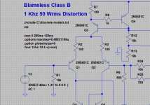
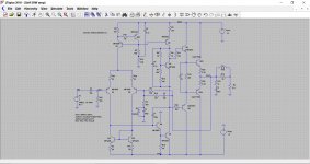
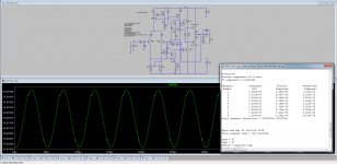
I went ahead and did a sim, but I don't know if it's OK.
The main problem I found is the bias current, because for lower currents I get weird sinusoids in the LTP, particularly at 20KHz.
THD is very good at 1KHz and 20KHz at the output. Also the square wave.
The main problem I found is the bias current, because for lower currents I get weird sinusoids in the LTP, particularly at 20KHz.
THD is very good at 1KHz and 20KHz at the output. Also the square wave.
There are lots of places within an amplifier where the voltages and currents don't resemble a sine wave. The voltage waveform on the collector of the transistor in the LTP that drives the VAS stage will look very distorted.
The weirdness you see at the LTP shows the good work done at correcting non linearities thanks to negative feed back.I went ahead and did a sim, but I don't know if it's OK.
The main problem I found is the bias current, because for lower currents I get weird sinusoids in the LTP, particularly at 20KHz.
THD is very good at 1KHz and 20KHz at the output. Also the square wave.
Of course this remark might be used by the anti nfb sect for negative opinions.
An op amp based amplifier shows very well nfb at work. You can see voltages and currents at the important points.
You'll see distorded voltages that do have the exact distortion as to result in a no distortion at the output. And do not look at currents, you will get scared at what's going on at Xover in a Class aB BJT amplifier. So scared you will not beleive the voltage at the output is just fine.
Posts #19 and #20 here :
Installing and using LTspice IV. From beginner to advanced.
I get around 0.0005% for my own sim.
Installing and using LTspice IV. From beginner to advanced.
I get around 0.0005% for my own sim.
Attachments
I don't get my sim to run with those parameters.
Of course I replaced mine with yours, but it stays running numbers, but not forward.
Of course I replaced mine with yours, but it stays running numbers, but not forward.
that is way better then similar circuits in reality. 0.02% THD is more likely
Q4 will drive 50 -100ma in clipping
Q4 will drive 50 -100ma in clipping
Last edited:
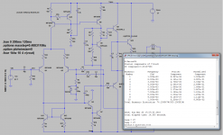
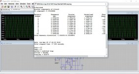
OK. I did that and it runs. But watch what happens with THD and sinusoidal when I sim for 20K.
I made two sims, both using lower input signal. One with my values and another one with yours.
Notice I just want to understand what is happening, or to see if something is wrong with my LTSpice installation.
As I had commented at the beginning, the 20K sinusoidal has spikes at LTP out, going to the VAS. That only seems to improve with higher bias.
Attachments
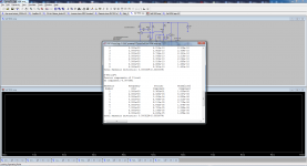
A couple of things to do.
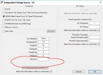
1/ You need to recalculate the timestep. If you retain the settings of 200ms and 120ms then we are looking at the last 80ms of the run.
So we take 80ms and divide it by 262144. The last number is the default setting in LTXVII so you should check this in your installation of LTIV.
This gives 0.080/262144 which is 0.00000030517578125 or 0.30517578125uS
That is entered as the timestep.
2/ You have to change the .four 1khz v(vout) to read .four 20khz v(vout)
(To see what the default setting is you run the sim, then right click the waveform screen and select <view> and <FFT>)
Attachments
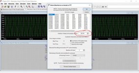

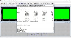
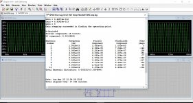
Why if I reduce the timestep to .8mS the THD increases?
It goes from 0.006% with .tran 0 200ms 120ms 0.30517578125uS
to 0.022% with .tran 0.8ms
It goes from 0.006% with .tran 0 200ms 120ms 0.30517578125uS
to 0.022% with .tran 0.8ms
You need to run the simulation for long enough to get a reliable result, and then for the best results to use just the last portion of the run... when it has all settled and is stable.
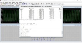
At 20kHz a sim time of 200ms is a bit excessive. You could try 500uS total run time and to start saving data after 100uS. Use a timestep of 0.0015258uS
Remember it is the measurement that needs the correct timestep, not the amplifier. It is a bit like measuring a real amplifier with incorrect equipment if it is not set correctly.
- Status
- Not open for further replies.
- Home
- Amplifiers
- Solid State
- Douglas Self amp simulation