Hi DiyAudio members !
I want to 1st order low pass a woofer at 140Hz with a series inductor before the Re driver.
R=Re+R_inductor
Le=Le+Le_inductor
Re=5.75 Ohm
Le=1.8 mH
R_inductor=0.68 Ohm
Le_inductor=4 mH
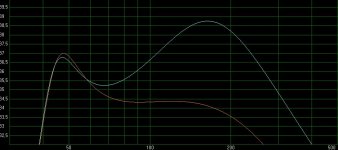
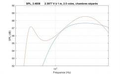
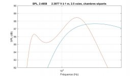
When i add a LP filter in EQ/Filter tab in WinISD Pro, it work's like i want (orange curve in black plot). But if i change directly the Re and Le values in driver parameters, it does'nt (cyan curve...).
When i use Matlab with my schematics (lumped parameter), i get the same bad result. First white plot is without filter, the the last one is with added impedance.
Should i expect this bad behavior of the LP ?
I want to 1st order low pass a woofer at 140Hz with a series inductor before the Re driver.
R=Re+R_inductor
Le=Le+Le_inductor
Re=5.75 Ohm
Le=1.8 mH
R_inductor=0.68 Ohm
Le_inductor=4 mH
When i add a LP filter in EQ/Filter tab in WinISD Pro, it work's like i want (orange curve in black plot). But if i change directly the Re and Le values in driver parameters, it does'nt (cyan curve...).
When i use Matlab with my schematics (lumped parameter), i get the same bad result. First white plot is without filter, the the last one is with added impedance.
Should i expect this bad behavior of the LP ?
Attachments
Last edited by a moderator:
Hi!
So you want to create a low pas filter in front of the existing complex impedance device, not with it.
Take a look at the impedance curve at the frequency you want to create a filter at. For instance, the Z at 180 Hz may be 5.3 Ohms. Use that to calculate your low pass filter. To get 6 dB down at 180 you must divide the impedance equally, so the added coil must be 5.3 Ohms at 180 Hz as well.
It's a starting point only though, as speaker impedances are complicated. To properly match a mid or tweeter adjustments will undoubtedly need to be made.
Erik
By the way, of course, this filter is additive to the existing speaker's electro-acoustic output. If it already rolls off at 6db/Octave starting at 180 Hz, then adding the coil will add 6 dB/Octave.
Hope this helps,
Erik
Hope this helps,
Erik
A passive low pass filter at such a low frequency requires the impedance peaks of the woofer to be flattened first. At least the peak that is highest in frequency. Otherwise you usually get a bump somewhere around 100 Hz. It is cheaper to implement an active filter, or put the woofer in a bandpass enclosure.
Hi DiyAudio members !
I want to 1st order low pass a woofer at 140Hz with a series inductor before the Re driver...
The easiest way of finding a solution is to use existing sim programs where
you can import the frd (spl vs.freq) and zma (impedance vs.freq)
of the driver. The Le of the driver is defined at certain frequency in order to
match the real inductive reactance of the driver. Manufacturers usually provide
Le parameter. Once you have speaker unit impedance defined (in a box), you don't
change it in simulation, just the filter values. Get yourself XSim program.
The only two variables that might change the response is inductor's Re and L.
First, let me say that i'ts a great pleasure to see answers to my post ! 😀 Thank's a lot ! "Hey ma, i'm not alone !"
I am an university student (mechanical ingeneering) and i try to practice conception procedure. For now, i have to produce a concept proof with only theoritical data. I'll do phisical tests next step.
I use T-S parameters of PartsExpress. I wans to do the model mysilf instead of using a software like WinISD etc. Of course, i use this software to see if i'm ok. The goal is to learn and correctly understand the theory ! 🙂
I choose the lumped parameter way instead of the cookbook method. The amplifier i used is bi amped. So filtering is active but i need to go passive for two woofers
The first time i see the second response bumb, i though that i make a mistake because WinISD show different curve. I change my Matlab script with a simple low pass filter apply to the curve instead of add filter parameter to the system impedance. The result was verry satisfying -> Too good to be true ! hahaha
What i understand from you reply :
- Stop using WinISD for filter checkup : download XSim to check my calculations
- Don't hesitate to post here if a have a doubt
- The bump in response mean a bump in impedance. Try to reduce this impedance peak will flaten response
- Vendor specs are good starting point but real life impedance measurement need to be acheived asap.
- I can control response mechanicaly with bandpass enclosure
From this understanding, i have one questions :
- I read that good alignment relate to symetry of impedance peaks. If i attenuate one peak, i lost this simetry. Is that a problem ?
- Is there a way to go bandpass enclosure and keep the driver's efficiency ?
Maybe you could practice phasor algebra to calculate
all the variables to get the desired response. That would
be realatively easy. You'd be converting between polar
and rectangular forms and the end result would be perfectly
accurate. You can assume the driver response alone to be
a flat line for starters.
I wasn't saying you shouldn't use WinISD, just mentioning
a simple alternate software. I've never tried WinISD.
Relative is relative 😛. Seriously though, I'd recommend this as an excercise in understanding firstly the basic interaction, and also the practical side of applying it to a speaker.Maybe you could practice phasor algebra to calculate all the variables to get the desired response. That would
be realatively easy.
Using xsim will take you to the same ends though, albeit with more guessing, but at a higher rate.. 😉 At a higher level of understanding a crossover simulator can become indispensable.
The information needed to do a simple crossover can be consolidated for a single point in the system by taking specific measurements, and these are the entry point for a conventional crossover simulator. The measurements are as follows:I use T-S parameters of PartsExpress. I wans to do the model mysilf instead of using a software like WinISD etc.
Driver frequency response (sound pressure level) taken at a suitable location, and phase. These two sets can be held in the *.FRD file format for use in most sims. Sometimes phase is derived from the response data and sometimes it is measured, there are caveats, just start somewhere.
Driver impedance and phase, which can be held in the *.ZMA file format.
Start with the assumption that components you place between the speaker and the amplifier won't change the fundamental behaviour of the speaker. They will change the electrical 'appearance' of the speaker with respect to the network applied. It comes down to two things..I read that good alignment relate to symetry of impedance peaks. If i attenuate one peak, i lost this simetry. Is that a problem ?
The filter network modifies the drive signal in a selective way, so you can change the response..
and the filter network has a complex interaction with the speaker impedance, which is primarily an impediment to the way you design the filter.
Look at the example of a woofer that has a rising impedance, and the requirement to apply a low pass filter at its top end. If a series resistor and capacitor is strung in parallel with the driver the combined impedance in the region appears resistive, simplifying the design of the low pass filter placed before it.
I'm not sure but I've thought of WinISD as a box simulator, and Xsim is a crossover simulator. Each has their uses.- Stop using WinISD for filter checkup : download XSim to check my calculations
The bump in impedance requires fancy filter work to avoid the bump in response. It is easy to do once you get the hang of it.The bump in response mean a bump in impedance.
Efficiency can be controlled with the enclosure. It is a direct trade with bandwidth, more of one means less of the other. That said, a bandpass box is usually not used at middle and higher frequencies.- I can control response mechanicaly with bandpass enclosure
....
- Is there a way to go bandpass enclosure and keep the driver's efficiency?
I'd recommend this as an excercise in understanding firstly the basic interaction said:The bump in impedance requires fancy filter work to avoid the bump in response. It is easy to do once you get the hang of it.
AllenB, it's a pleasure to read your reply. Thank you ! Re-open my linear algebra school book may help but i think my flaws are in the understanding of the analogue impedance and mobility model. That make me confused on wich assumption postulate et wich one avoid. Altough, I realize now that playing in the low end can easely be tricky and expensive.
I found mistakes on my design two day after buying parts... But the good news is that there must be a simple way to make a good design from it because theses parts are used in an existing product.
I'm tempted to show an abstract of my works but it's hand writed. Maybe i'll post it.
The impedance is simply a real (resistive) component vector summed with an imaginary component consisting of a reactance such as exhibited by the opposing capacitance or inductance, taken at some point in the circuit. It can also be expressed as a single magnitude component with phase (+ or -).
These forms of representation also apply to current (used in the solution process), and Voltage, where the magnitude and phase represent the signal, eg the drive signal and therefore the changes to the speaker response.
These forms of representation also apply to current (used in the solution process), and Voltage, where the magnitude and phase represent the signal, eg the drive signal and therefore the changes to the speaker response.
I try to draw my schematics with Matlab Simulink and it work's !
I take the module of the sum of speeds Vx+Vv and compute the pressure Ps and the sound pressure Spl.
Spl=20*log10(Ps/Pref);
There is about 30 other equation...
Is there a way to easy extract electrical impedance and total impedance from the mobility analogue circuit, or i need to do all the impedance analogue too ?
Thank you 🙂
Attachments
Z=V/i
Take voltage at voltage source or between crossover inductor and Re
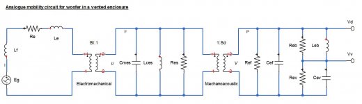
Usually the radiation mass and resistance get moved over to the mechanical side and lumped in with the rest.
Those in teh mechanical part should probably be called (assuming they need to be prefixed with C,L,R) Cmms, Lcms and Rrms (which is actually 1/Rms)
Lces, Cmes and Res are usually reserved for those mechanical values referred to the electric side through the transformer.
Take voltage at voltage source or between crossover inductor and Re
Usually the radiation mass and resistance get moved over to the mechanical side and lumped in with the rest.
Those in teh mechanical part should probably be called (assuming they need to be prefixed with C,L,R) Cmms, Lcms and Rrms (which is actually 1/Rms)
Lces, Cmes and Res are usually reserved for those mechanical values referred to the electric side through the transformer.
Last edited:
- Status
- Not open for further replies.
- Home
- Loudspeakers
- Multi-Way
- Does an inductor in series affect driver's inductance (Le) ?