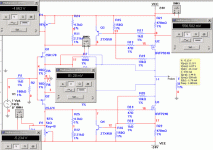
look at f5 circuit.
when i disconnect GND from resistor of JFET souce pin, i found better performance in my simulation circuit.
in orignal f5 circuit , i got distortion =0.02% ,gain = 5 , dc offset=250mv
in no-ground f5 circuit , i got distortion=0.009%, gain=0.8(too small) dc offset = 80mv
BTW, my attachment pic is not mine , which is from website.
i use multisim from NI to simulate F5.
can somebody tell why ,which one is better.
Attachments
I don't have the original circuit but looking at your attachment it seems you have increased the negative feedback, hence the reduction in gain and distortion.
If you take a look at your figures, you'll see that the distortion per dB of gain, is higher in the 0.8dB gain version.
Magura 🙂
Edit: Not that I see a reason to lower the distortion of the original circuit??
Magura 🙂
Edit: Not that I see a reason to lower the distortion of the original circuit??
- Status
- Not open for further replies.