Hi,
I'm trying to build a rtp5 linestage according to the design by mr Allen Wright(third schematic from the top):
Schematics.
I had most of the parts present so this seemed like a nice and easy build but it is giving me quite a headache.
The way I've build it now it seems to have two functions but not the intended one. First it acts as a very effective fet destroyer. Every time i power down and then power up again the bootstrap fets in the output stage go to fet heaven and i don't understand why.
the anode voltage on the output cathode followers is about 150V, cathode voltage at about 70V, grid at about 66V and running at about 10mA each. The only difference from the original schematic is higher grid/gate resistors and 4,7K in stead of 47K in the bootstrap bias circuit. Why do i keep blowing these fets? I used 5687's for the output.
Second the unit is a very good and stable noise generator. I've scoped back the noise and it's first appearance is the anode of the input tube. Thus i figured i needed some anode stoppers and while it helps the noise doesn't go away even after going as high as 100R and there is very little difference between 22, 40 and 100R. The noise is present all around the output stage slcf except for the power supplies which are all on target and pure dc.
The input tubes are 6dj8's running at about 5.5 mA each, so a bit higher then specced but lowering the running current hasn't helped. Grid at 0V, cathode at 1.15V, anode at 66V. CCS as per the cookbook, p4 of mod's and maybe's best.
What could i do for the fet destruction and for the noise? 🙁
Thanks,
Joris
I'm sure Allen will have some comments. My first thought was, "Easy build?" Not at all- without using a well-laid-out board, the chances of oscillation are near 100%. And I think that may be the root of your problems. Cascodes are tricky and insanely power supply sensitive, and using high transconductance tubes makes things even trickier.
This is a very advanced and challenging project. Very high performance, but not something to just throw together.
This is a very advanced and challenging project. Very high performance, but not something to just throw together.
Those circuits are not intended as "paint by numbers" DIY projects, they are there to show that our designs are very different to most current products that are just 50's and 60's designs re-issued in modern boxes.
That map, and you, don't show the protection zeners the fets need. If you put a 10V zener from gate (cathode) to source (anode) on those fets, they will stop blowing.
But If you've sent the time and effort to make up a FVP-5 line stage, is there any way you can make the far better sounding all tube version, the FVP-5A?
It takes another tube per channel, but is really on another level as far as sound quality goes. The difference between these two designs had me rethink the sonic value (or otherwise) of MOSFETs in an audio signal path.
Noise? As SY has suggested, it's most likely oscillation. Are the gate stopper R's RIGHT on the tube socket pins? I mean RIGHT on the socket, not 1/4".5mm away! 6DJ8s are VHF RF tubes after all.
Regards, Allen
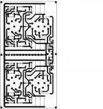
I just looked over your PCB layout and I'm confused.
I cannot see where Pins 1 & 9 are, as they all seem to be equallu spaced, so cannot orientate.
And in one tube you seem to have one pin unconnected, which if it's pin 9 that's ok, but on the second tube it appears that you have TWO pins unconnected.
???????????????????????????????????????
Regards, Allen
I cloned an FVP4 or 5 several years ago, cannot remember the model at the moment but it was from Allen's preamp book which I bought. It used 6922 or
6dj8's and IRF830's I believe and was quite impressed and wrote Allen about it, singing its praises.
He responded that if I thought it was that good I should try the the FVP5A, which I then cloned, superreg and all. While I would not say it was a night and day difference I thought the FVP5A was "smoother".
I still have it after many years, the only amp I have never cannibalized which knowing myself is unheard of.
In other words, its well worth the effort.
Andrew
Hi,
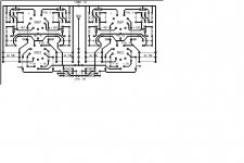
Just looked at the posted pcb and realized it is the wrong layout. My sincere apologies for this error. The mistakes around the output tube have been corrected but i can't find the correct layout now. I'll keep searching.
Thanks for the hint on the zeners mr Wright. My FVP5 is due for service anyhow so I'll try to change it to the FVP5A version when i'm at it to
regards,
Joris
Hi,
Well i didn't have the layout anymore so I made a new one. The dimensions may vary slightly from the actual unit but not by much and should give a good impression. This is bottom view for the tubes only. I've marked pin number one and supply voltage inputs as well as the values for resistors shown as jumpers.
I did try to get those gridstoppers rather close but maybe not close enough...
regards,
Joris
Attachments
Joris,
the grid stoppers should be soldered on the tube socket pins as close as possible, in other words the resistor body should be right against the socket connection, touching it. The idea is to have the grid stopper as close to the tube grid as possible. Perhaps you may want to consider soldering one end of the grid stopper directly to the tube socket and the other end to the PCB.
While it may not be pleasing to the eye, it will be pleasing to the ear and once its installed you will not see it anyway😉
Andrew
Jazz,
1/ Didn't realise you were doing a RTP5 line stage, I thought we were talking about the FVP-5 unbalanced stage.
1/ The grid stoppers for the 6922 are close, and MAY be OK, but as Andrew says, they should really be AT the tube pin, even if you have to "hard wire" them there.
The grid stoppers distance for the 5687 are FAR too long - I'd be surprised if it doesn't oscillate horribly! They must be moved very much closer.
This sort of thing is what tends to gives high gM tubes a bad name. People say "Oh, I've got grid stoppers there but it still hums, buzzes and is microphonic", but in essence they may have resistors, but not "grid stopper' resistors!
Regards, Allen
would a ferrite bead be helpfulf around the "real" gridstopper ?
Why not build P2P without a board (there are not so many parts) ?
Why not build P2P without a board (there are not so many parts) ?
I agree, I believe all one-offs should be built P2P. Far easier to optimise signal paths, far far easier to change things in the future when the urge hits you.
But I disagree with the use of ferrite beads in audio, they bring too many odd unpredictable effects for me. A grid stopper of adequate value RIGHT where it should be will handle oscillations perfectly. And that means: on ALL grids!
Regards, Allen
But I disagree with the use of ferrite beads in audio, they bring too many odd unpredictable effects for me. A grid stopper of adequate value RIGHT where it should be will handle oscillations perfectly. And that means: on ALL grids!
Regards, Allen
The way I've build it now it seems to have two functions but not the intended one. First it acts as a very effective fet destroyer. Every time i power down and then power up again the bootstrap fets in the output stage go to fet heaven and i don't understand why.
the anode voltage on the output cathode followers is about 150V, cathode voltage at about 70V, grid at about 66V and running at about 10mA each. The only difference from the original schematic is higher grid/gate resistors and 4,7K in stead of 47K in the bootstrap bias circuit. Why do i keep blowing these fets? I used 5687's for the output.
Your experience with the FETs is interesting. I recently finished an active crossover which included the line stage of the RTP5 (with six of the SLCF output buffers in all), and I had problems with these FETs too. I found that the upper IRF710s would often test faulty on power-up, with no current at all through the stage. After a few MOSFET replacements the whole thing eventually worked, and I came to the conclusion that the problem was electrostatic gate insulation damage resulting from shoddy packaging from the supplier (and possibly the odd one that I carelessly damaged myself). The very high resistor values (1M0 and 1M5) around the gate of the bootstrap transistors mean that if there is any gate leakage the circuit won't work at all.
Since then the unit has been working fine for several months, so I conclude that power-up overvoltage is not an issue - especially since I run mine at a higher B+ (300V) than the original. I may still take up Allen's suggestion of a protection Zener, though.
As I understand it, the original 47K resistor is there to try to isolate the effect of the voltage-dependent capacitance of the MOSFET from the signal output, so you may want to put this in place of your lower value.
Alex
still not there...
Hi,
Ok, given the comments I did a little experimenting:
1) replace the grid stoppers on one channel only for the 5687 output cf, soldered directly to the tube socket (300R). No effect
2) replace the grid stoppers on one channel only for the 6922 input tube, soldered directly to the tube socket (300R). No effect.
3) remove the extra 4k7 (should be 47K) between the 1M5 and 330R grid resistors on the 5687 output cf on one channel. No effect (reason for this is i don't have the problem with my fvp5 and that doesn't have these).
4) replace the grid stoppers on one channel only for the 5687 output cf, soldered directly to the tube socket (680R). No effect
5) replace the grid stoppers on one channel only for the 6922 input tube, soldered directly to the tube socket (680R). No effect.
6) check supperreg etc again, nothing.
7) ok let's see if these two halves (input 6922 and output 5687) can behave independently and the cause isolated. Remove the grid resistor connecting the 6922 anode to the 5687 grid (one channel only) and put a 68K resistor from grid to ground on the 5687.
Hey, there's no more noise on the output of that channel, it is in fact dead silent. The other channel is the same as before. On the input tube both channels measure exactly the same (ie some 20mv of noise). The isolated output stage runs at only 6mA and it's anode is at about 120V, grid 0V and cathode 6V.
Anybody got a suggestion on what to try next?
mzzl
Joris
Hey,
Ok a separate reply to some of the other comments.
First why not a p2p build? well I had the components for a pcb build and not for a p2p build (no turret terminals and such). Plus whenever i go p2p it always seems to end up like a mess. The design of the pcb forces me to think about certain things earlier. In this case a pcb based version just suited me better given the desing brief and I have no preference for either. I'll leave those discussions for you guys, I just want to build and try out various designs with what i've got. If I get it to work I'm happy.
I do realise i might not get the full potential of the design itself but i might get an idea of it's 'character'. Even if I achieve only 70-80% of the possible potential it's ok. I don't have the skills for more anyway i believe. Then again i figure 70-80% of an rtp5's potential still gives me more then i could buy in the shop and building it has given me enough fun and satisfaction to make up for the rest.
Regarding the diodes i think it might have more to do with dc values moving around during start-up and power down. During the time the tubes heat up these move around and might exceed the Vgs rating (20V) of the fet's. I didn't dare to pose this question earlier but still think that is the culprit. Mybe someone else can comment on that?
grtz,
Joris
btw, that's a very nice chassis tsatakis and more. I hope it will work for you. What design are you building?
I built a FVP5 with a IRF610 on the top. It rn for about five years without issue concerning the FET. I built it P2P and once I had the power supply quiet enough I never got any noise or hum.
The FET sets its own gate to drain voltage depending on the amount of current it is expected to pass so should never exceed the 20V rating.
Since you have noise and exploding FETs I think you still have oscillation issues. What is the distance between the 6922 anode and load resistor - might you need an anode stopper?
Otherwise how does it sound? If its bright and harsh then that again points to instability.
Shoog
Last edited:
Hey shoog,
Thanks for your reply. I didn't have time to experiment any further and will go on next week. I didn't have any of these problems with my fvp5 as well and that one has run for about 8 years now. I still love it and I even managed to get the phono stage working on that one as well though it probably isn't conforming to spec.
I regret my earlier comment about vgs being the probable cause for the fet failure. I think that was to much of a statement with insufficient question. I did check those ratings and tried to measure it but things are moving around to wildly for me to monitor during heat up and i do not have the equipment for time tracked measurements. Thus i don't really know. Anyway the diodes solve the problem (thank you mr Wright!).
I did try anode stoppers at first but took them out when trying the changes with the grid stoppers. I'll try them again with the changed grid stoppers. good point maybe i need both. Then again in that case the pcb would be flawed fundamentally and i'd need to rethink the whole thing.
What's bugging me is the noise is there at about 20mV and within the standard audio range. I don't measure anything else up to 10MHz (scope limit). How likely is it that i've got oscillation above that? The components used are just about the same as in my Fvp5, why would they behave differently now?
What's next to try is to change both channels and see if that has some effect. Maybe one channel still oscillating gives enough interference between the two channels to negate the effects of the changes to the one channel. I'll also try and see what happens when i connect the unit to the AX balanced in stead of se to the f5 proto.
All else being the same i feel like i'm out of my league here. I've never encountered this sort of thing before. So any idea is welcome.
grtz
Joris
Edit: Oh forgot, when playing the unit sounds just fine. I just don't get the noise out.
Last edited:
Gents,
Noise in a RTP-5/FVP-5 gain stage is 99% certain to be oscillation. The production SVP-2's have had one instance of reported noise, but he had poweramps with some 40dB of gain! And when we researched this, the noise was in the SLCF section (circa 1mV), not the gain stage.
** What voltages do you get on the triodes in the cascode section?
** But what gain are you running in that first gainstage?
** And how muchgain does your poweramp have? And what speaker sensitivity?
** What PS regulation are you using? - if not a SuperReg, then all bets are off!
** The cascode gain stage has very poor PSRR, and relies on a dead quiet, dead stable powersupply. If you make a RTP-5/FVP-5 with phono but without a SuperReg, you also will certainly have motorboaring...
** Have you posted the PCB layout you have finally used? Layout determines stability.
Regards, Allen
- Status
- Not open for further replies.
- Home
- Amplifiers
- Tubes / Valves
- DIY rtp5 help please?