Hi,
First off, a disclaimer: I am not well versed in electronics, so if this is a dumb question forgive me.
I want to try my hand at building some inexpensive baluns to send a line-level audio source via CAT5 from the output of one amp to another amp on the opposite side of the house (about 80-100 feet).
There are plenty of sources for these on-line but I do not wish to spend over $100 for a pair of these. Plus, I just may have the necessary parts in my "junk drawer" to cobble something together.
I've searched the forums and could not find a straight-forward answer, but did manage to determine I need a transformer to convert the impedance.
Now here comes the dumb question part:
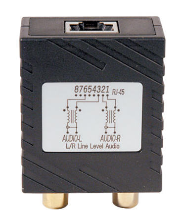
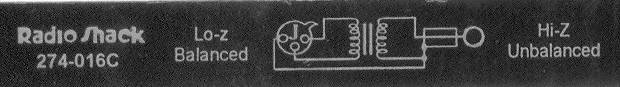
I have a bunch of these old Radio Shack Hi-Z/Lo-Z adapters laying around (part no 274-016C). Can I yank the transformer from them and use them for this purpose? I could not find any specs on what the impedance conversion is on them is.
So to rephrase my question in pictorial:
Can I make 2 of these:
out of 4 of these:

(plus the right connectors obviously)
First off, a disclaimer: I am not well versed in electronics, so if this is a dumb question forgive me.
I want to try my hand at building some inexpensive baluns to send a line-level audio source via CAT5 from the output of one amp to another amp on the opposite side of the house (about 80-100 feet).
There are plenty of sources for these on-line but I do not wish to spend over $100 for a pair of these. Plus, I just may have the necessary parts in my "junk drawer" to cobble something together.
I've searched the forums and could not find a straight-forward answer, but did manage to determine I need a transformer to convert the impedance.
Now here comes the dumb question part:
I have a bunch of these old Radio Shack Hi-Z/Lo-Z adapters laying around (part no 274-016C). Can I yank the transformer from them and use them for this purpose? I could not find any specs on what the impedance conversion is on them is.
So to rephrase my question in pictorial:
Can I make 2 of these:
out of 4 of these:
(plus the right connectors obviously)
I did about the same thing, some years ago.
Use both low impedance windings for the Cat5 wires.
Use the high impedance windings for the input and output.
Don't jumper the low to high impedance windings.
Use both low impedance windings for the Cat5 wires.
Use the high impedance windings for the input and output.
Don't jumper the low to high impedance windings.
well, I tried this with mixed results:
First, I did just one channel with about 10 feet of CAT5 and the sound was great. I had one channel plugged in with a regular RCA cable, and the other with my 10' cat5 hack job and could hear no noticeable difference, so I thought I was good to go.
I re-made the cables, this time with both channels and about 150' of CAT5. This time the results were not so good. There was so much noise on the line it was not usable. Oh well, I guess this is a bust.
I might try ordering some commercially made baluns to do the job.
The connections on that commercial unit aren't making any impedance conversion at all, there's no need with audio frequencies other than to match voltages (impedance of cable starts to become significant when the cable gets 1/8-1/4 wavelengths of the signal, for audio that's over a mile/1.6k).
From the look of the diagram on the side, the magnetics in the box are only to increase the common mode impedance to reduce the chance of picking up radio interference and the like as each winding is in series with the respective ethernet conductor, not across a pair.
From the look of the diagram on the side, the magnetics in the box are only to increase the common mode impedance to reduce the chance of picking up radio interference and the like as each winding is in series with the respective ethernet conductor, not across a pair.
Cat5 to RCA video signal only?
Can I DIY to make a connector from the cat5 to video only rca male input?
Thanks guys,
Richard
Can I DIY to make a connector from the cat5 to video only rca male input?
Thanks guys,
Richard
Cat5 to video will require a balun at each end because video is 75 ohms and cat 5 is 100 ohms and the impedance matching will be important at video bandwidth (~4+ MHz).
An active circuit based on opamps will work better and might actually cost less. Especially since good audio transformers are expensive. Use a high drive voltage for a high SNR.
If you're sending digital audio, use RS485 transceiver chips wired to only transmit or receive. Don't reinvent the wheel if there's already one that works very well.
In any case, unused pairs can be used as grounds. (And for shielded CAT5, the shield can obviously be a ground.)
If you're sending digital audio, use RS485 transceiver chips wired to only transmit or receive. Don't reinvent the wheel if there's already one that works very well.
In any case, unused pairs can be used as grounds. (And for shielded CAT5, the shield can obviously be a ground.)
Noticing that I'm about 11 years late to the game, here. But, who knows? you could still be looking for that elusive circuit. The schematic shown on your device in the first picture is not hooked up like a transformer; it's hooked up as a common mode choke. This is common to run long lines through as any noise or interference on a twisted pair will be on both wires (the purpose of twisting them) in other words it is common mode noise. When sent through a common mode choke, as long as the two coils are wired and wound correctly, the magnetic fields cancel on signals common to both; therefore canceling out the noise (as it appears on both wires). This will happen on either a cm choke or an op-amp circuit which uses a differential input structure. The circuit is processing the difference of the two wires; therefore, any signal which has equal amounts on both wires literally gets subtracted out.
- Home
- Design & Build
- Parts
- DIY RCA - cat5 balun help