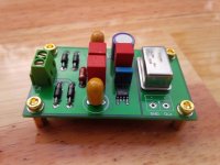
PCB Clock that I have perfected.
I use 5V LT1763 (low noise) to supply power to the crystal.
I use 5V LT1763 (low noise) to supply power to the crystal.
Attachments
Now all you have to do is invent a perfect way to connect it to a circuit.
I'm thinking about that, can you give me advice 🙂
Sorry, no. I know that I don't know enough to do it perfectly, or even competently, as my background is audio and radio rather than digital and mixed-signal.
Clocks generally are best placed next to the device they provide the clock signal too. Sending a clock signal through those sort of connectors is not going to do the signal integrity of the clock any good... Use a small RF with co-ax cable
AC on board, not the best idea... DC only would be best.
Its basically a crystal with a power supply... Is it going to improve an on board clock?
AC on board, not the best idea... DC only would be best.
Its basically a crystal with a power supply... Is it going to improve an on board clock?
Yes, it is generally a good idea to keep RF oscillators and PSUs well apart unless you want hum sidebands. You have carefully checked the output spectrum? There is more to low noise (i.e. low jitter) oscillator design than merely feeding a packaged oscillator from a low noise regulator.
- Status
- Not open for further replies.