Hi all,
First post. I searched first.
Assembled the Chinese diy kit of jhl hood headphone amp which also carries "zero zone" on PCB. Love the sound. Can't sonically detect anything wrong with it. However one half is running hotter than the other. There are two variable resistors which I measured were both set half way. Any advise on how to fine tune?
Many thanks in advance!
Roman
Attachments
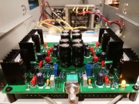
Hi, what power is that amp? The heatsinks and transformer look very small. Can you provide a link to the amp?
Not sure ebay links are allowed but the schematics published with the item is attached.
The item is called "JLH HOOD 1969 Class A Headphone Amplifier Small Power Amplifier Pre-amp DIY KITS".

The item is called "JLH HOOD 1969 Class A Headphone Amplifier Small Power Amplifier Pre-amp DIY KITS".
Those pots is to set DC offset at the outputs. but it's useless. the offsett is all over the place anyhow. you need a DC servo or AC couple the amp. i just finnished one of these myself. and the offset goes from 900mV to -200mV depending on temperature.
AudioSan, I saw re offset on this forum. Is it DC component of the output? I checked with oscilloscope, as far as I can see when there's no signal both output channels are on the Zero.
At the moment the fact one side is a lot hotter than the other bothers me more. Is it R1 and R2 as per above schematics?
Before assembly I was checking components. "100" Caps for example were from 99pF to 105pF. Resistors more or less stable.
At the moment the fact one side is a lot hotter than the other bothers me more. Is it R1 and R2 as per above schematics?
Before assembly I was checking components. "100" Caps for example were from 99pF to 105pF. Resistors more or less stable.
Member
Joined 2009
Paid Member
There's no shame in using an output capacitor, it blocks dc end of story.
This isn't the JLH69 is it?
This isn't the JLH69 is it?
Yes, it really is a JLH design but for reference, it follows a specific headphone amplifier design published in 1979 and subsequently upgraded in 1980. Unfortunately, TCAAS notes don't describe construction or set-up which would probably help with thermal and DC offset issues. The function and dissipation in either power transistor is not the same in these JLH designs so I don't think you could expect the temperatures, given that they are mounted on separate heatsinks, would be the same either.
The Class-A Amplifier Site - JLH Headphone Amplifiers
The Class-A Amplifier Site - JLH Headphone Amplifiers
Yes, it really is a JLH design but for reference, it follows a specific headphone amplifier design...
Great info, thanks!
I am not comparing the two power transistors in one channel, but across the two channels. Bot of them in one channel are a lot hotter than both of them in the other.
AudioSan, I saw re offset on this forum. Is it DC component of the output? I checked with oscilloscope, as far as I can see when there's no signal both output channels are on the Zero.
At the moment the fact one side is a lot hotter than the other bothers me more. Is it R1 and R2 as per above schematics?
Before assembly I was checking components. "100" Caps for example were from 99pF to 105pF. Resistors more or less stable.
measure DC voltage across the output. there is a snowballs chance in hell this is 0mV on this amp.
Check that D1/2/3/4 are all the correct way round.
That would manifest in rail voltage not be +12 and -12, thats easy to check, will do. Also, pretty sure all the diodes are the right way round. But worth checking, thanks!
measure DC voltage across the output. there is a snowballs chance in hell this is 0mV on this amp.
I did, with oscilloscope. They are on the Zero DC. The trace would have jumped up or down, but it stays on the same level as if I touched the ground. Hm... maybe I don't know my oscilloscope - something with "DC / AC coupling" perhaps... OK, will double check. With multimiter too.
There's no shame in using an output capacitor, it blocks dc end of story.
This isn't the JLH69 is it?
Go for audio grade 10mfd...sounds awesome...and no risk of speaker damage
Great info, thanks!
I am not comparing the two power transistors in one channel, but across the two channels. Bot of them in one channel are a lot hotter than both of them in the other.
Chinese stuff...the transistors could be fake...try replacing them from proper sources
The standing current of this amplifier should be 100 m.a. equivalent to a voltage drop of .051 volts across the 5.1 Ohm resistors in each channel. Q1 and Q2 are PNP transistors so if the voltage on the base of these needs to be less positive than the supply rail - the less positive the more current these will conduct.
A number of the resistors have values starting with 47, e.g. 470R, 4.7K, and 47k.
I have seen resistors whose colours present as the value sought for but on measuring I find they are something else.
It would be worth checking the values you have for R3 and R4.
Edit: The original article appeared in Hi Fi News & Record Review January 1979 pp81-85 referring back to this the output stage standing current was specified at 110 m.a. The version presented here will draw more current than this as R9 and R10 have been decreased in value from 3.3k to 2.2k. If heat is worrying then you could fit the original value resistors.
Last edited:
...If heat is worrying then you could fit the original value resistors.
That's the advice I was looking for! 🙂 On resistor colours - I can't read them anyway! I was using the multimeter during soldering. 😉 Will check voltage drops.
Also thanks to the others! I will check, if not too expensive, will swap the transistors. The whole thing cost me 12 GBP.
For what it is worth the transistors specified for the original design were 2N4922 - 3A devices in a TO-126 package.
Your TIP41's in TOP66 packages are rated at 6A.
One could argue the kit supplier has specified a higher rated part in the interests of component reliability and longevity with a view to the higher output stage standing current.
Kit suppliers have their reputations at stake unlike those anonymous sources supplying re-labelled semiconductor product. Audio kit supply seems to have become very competitive in which case there will be a strong incentive to get things right.
You could do a little more investigation in this context before deciding whether or not to replace your output transistors.
The minimum load for the original design is 8 Ohms however the recommended load is 35 Ohms or more. The THD specifications are for 100 Ohms 0.014% at 100Hz, 0.007% at 300Hz, 0.008% at 1kHz, 0.017% at 3kHz, and 0.044% at 10 kHz - these exclusively second harmonic.
- Home
- Amplifiers
- Solid State
- DIY JHL1969 newbie question