Hello,
I am not an electronic engineer and my english is poor.
Sorry for my mistakes.
I work on this amplifier for a few month with MicroCap 12.
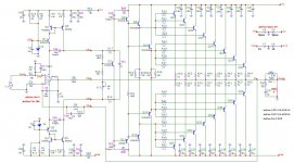
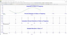
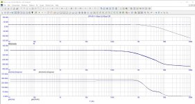
Here is the schematic, distortion with 1Watt output and phase diagram.
What is your opinion and your comments?
The power supply will be a SMPS from HYPEX + - 64V
I am not an electronic engineer and my english is poor.
Sorry for my mistakes.
I work on this amplifier for a few month with MicroCap 12.
Here is the schematic, distortion with 1Watt output and phase diagram.
What is your opinion and your comments?
The power supply will be a SMPS from HYPEX + - 64V
Attachments
Looks like a variant of the Alexander Current Feedback amp, but with many, many more output transistors. It lacks the offset servo that Mark Alexander had in his design.
Nice work , nice topology. Can you check this, may be help you.
Attachments
Last edited:
Thank you for your comments.
I started sourcing the components.
I am going to pair the power transistors
I started sourcing the components.
I am going to pair the power transistors
I want a quiescent current of 100 mA by adjusting X11.
I know that the power dissipation will be around 100W, each way, without signal.
I have two big aluminium dissipators (9kg each).
Do you see a possible problem?
I know that the power dissipation will be around 100W, each way, without signal.
I have two big aluminium dissipators (9kg each).
Do you see a possible problem?
Hi
For best thermal tracking :
Q8 and q11 must be not connect main heatsink.
Bias transistor , drivers and out transistors thermally couplet on main heatsink.
For best thermal tracking :
Q8 and q11 must be not connect main heatsink.
Bias transistor , drivers and out transistors thermally couplet on main heatsink.
Yeah, I’ve always had the best result if the predrivers were run cooler with less temperature swing than the drivers/outputs. And for best thermal tracking and output transistor power sharing, only ONE driver transistor, not multiples. Consider MJW0281/0302.
Thanks for your advices.
"Q8 and Q11 on another heatsink"
I have never heard this remark but I will follow it.
"Q8 and Q11 on another heatsink"
I have never heard this remark but I will follow it.
Hello WG_SKY
If I understand, you perfer one pair of MJW0281/0302 to drive the 2 x pairs of MJL4281/4302 instead of two pairs of MJE15030/15031 ?
And the reason is to be sure that all the power transistors are drived by the same signal !
Two pairs of transistors, even paired, do not give the same result ?
If I understand, you perfer one pair of MJW0281/0302 to drive the 2 x pairs of MJL4281/4302 instead of two pairs of MJE15030/15031 ?
And the reason is to be sure that all the power transistors are drived by the same signal !
Two pairs of transistors, even paired, do not give the same result ?
The two separate 1503x may not run at exactly the same *temperature*. Then there will be a mismatch in bias between the groups of outputs. It’s already hard enough keeping a long bank of the same outputs close enough to each other in temperature, and TO-220’s are notoriously difficult to heat sink correctly. You don’t want these imbalances growing and potentially getting out of control.
I Have a lot of MJL4281/4302.
Can I use it for Driver, instead of MJE15030/31 ?
With MC12 simulator, one pair of MJL4281/4302 is better than two pairs of MJE15030/31.
Can I use it for Driver, instead of MJE15030/31 ?
With MC12 simulator, one pair of MJL4281/4302 is better than two pairs of MJE15030/31.
AFAIR: With a bipolar emitter-follower output stage the optimal bias is one thermal voltage (Vt) across the emitter resistors.
Vt = kT/q
k = 1.38E-23 J/K (Bolzman's constant)
T = absolute temperature in K (so 300 K = 27 ºC)
q = 1.602E-19 C (elementary charge)
So you're looking for about 26 mV at room temp. I can't for the life of me remember if it's Vt across each emitter resistor of if it's Vt across both emitter resistors. I think it's across both.
Douglas Self writes quite a bit about it in his Audio Power Amplifier Design book.
The design reminds me of an old Linear Tech (or ADI) app note.
Tom
Last edited:
Good old HP Journal from February 1971, page 11-16
https://www.hpl.hp.com/hpjournal/pdfs/IssuePDFs/1971-02.pdf
https://www.hpl.hp.com/hpjournal/pdfs/IssuePDFs/1971-02.pdf
I Have a lot of MJL4281/4302.
Can I use it for Driver, instead of MJE15030/31 ?
With MC12 simulator, one pair of MJL4281/4302 is better than two pairs of MJE15030/31.
Yes, you can use the same driver as the outputs. I do it all the time with MJL21194’s. I only suggested the 0281 because it is “big enough” to replace a pair of 15030.
Don’t believe everything a simulator tells you, though. I doubt you would be able to tell a difference in he sound. It *will* give you less trouble in and actual amplifier that doesn’t have all perfectly matched transistors, and are all mounted to ever so slightly different thermal environments.
So you're looking for about 26 mV at room temp. I can't for the life of me remember if it's Vt across each emitter resistor of if it's Vt across both emitter resistors. I think it's across both.
Douglas Self writes quite a bit about it in his Audio Power Amplifier Design book.
The design reminds me of an old Linear Tech (or ADI) app note.
Tom
The app note is attached in Post #3.
Most of the time, with amps this big you end up running them under biased anyway. 26 mV across a tenth or two gets you a *lot* of heat with than many output transistors. Big *** EF3’s tend to get very low crossover distortion even with less than optimum bias. If you do plan plan on running optimum bias, plan accordingly for the heat. If you plan on sizing the heat sink for sustained high power operation it will be big enough. If what was planned was for “normal” listening levels only - optimum bias at +/-64V supplies, with 8 output pairs per channel, it might surprise you how much you’re dissipating at idle.
- Home
- Amplifiers
- Solid State
- DIY amplifier: OPA 1611 + Bipolar transistor